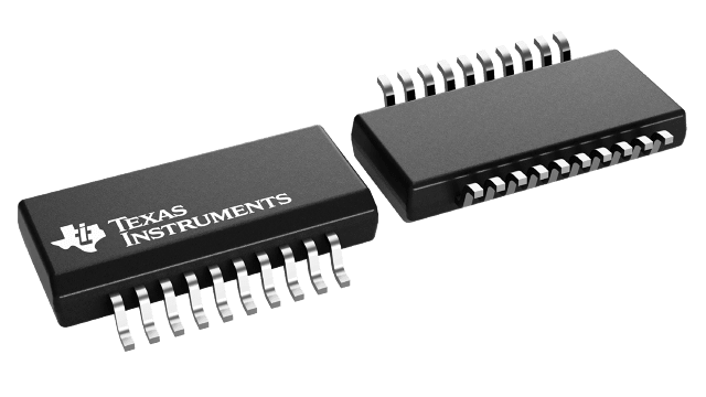
パッケージ情報
| パッケージ | ピン数 SSOP (DBQ) | 20 |
| 動作温度範囲 (℃) -40 to 85 |
| パッケージ数量 | キャリア 2,500 | LARGE T&R |
PCA9518 の特徴
- Expandable Five-Channel Bidirectional Buffer
- 400-kHz Fast I2C Bus
- Operating VCC Range of 3 V to 3.6 V
- 5-V Tolerant I2C and Enable Input Pins to Support Mixed-Mode Signal Operation
- Active-High Individual Repeater Enable Inputs
- Open-Drain Input/Outputs
- Lockup-Free Operation
- Supports Multiple Masters
- Powered-Off High-Impedance I2C Pins
- I2C Bus and SMBus Compatible
- Latchup Performance Exceeds 100 mA Per JESD 78
- ESD Protection Exceeds JESD 22
- 2000-V Human-Body Model (A114-A)
- 200-V Machine Model (A115-A)
- 1000-V Charged-Device Model (C101)
All trademarks are the property of their respective owners.
PCA9518 に関する概要
The PCA9518 is an expandable five-channel bidirectional buffer for I2C and SMBus applications. The I2C protocol requires a maximum bus capacitance of 400 pF, which is derived from the number of devices on the I2C bus and the bus length. The PCA9518 overcomes this restriction by separating and buffering the I2C data (SDA) and clock (SCL) lines into multiple groups of 400-pF segments. Any segment-to-segment transition sees only one repeater delay. Each PCA9518 can communicate with other PCA9518 hubs through a 4-wire inter-hub expansion bus. Using multiple PCA9518 parts, any width hub (in multiples of five) can be implemented using the expansion pins, with only one repeater delay and no functional degradation of the system performance.
The PCA9518 does not support clock stretching across the repeater.
The device is designed for 3-V to 3.6-V VCC operation, but it has 5-V tolerant I2C and enable (EN) input pins. This feature allows for translation from 3 V to 5 V between a master and slave. The enable pin also can be used to electrically isolate a repeater segment from the I2C bus. This is useful in cases where one segment needs to run at 100 kHz while the rest of the system is at 400 kHz. If the master is running at 400 kHz, the maximum system operating frequency may be less than 400 kHz, because of the delays added by the repeater.
The output low levels for each internal buffer are approximately 0.5 V, but the input voltage of each internal buffer must be 70 mV or more below the output low level, when the output internally is driven low. This prevents a lockup condition from occurring when the input low condition is released.
A PCA9518 cluster cannot be put in series with a repeater such as the PCA9515 or another PCA9518 cluster, as the design does not allow this configuration. Multiple PCA9518 devices can be grouped with other PCA9518 devices into any size cluster using the EXPxxxx pins that allow the I2C signals to be sent or received from one PCA9518 to another PCA9518 within the cluster. Because there is no direction pin, slightly different valid low voltage levels are used to avoid lockup conditions between the input and the output of individual repeaters in the cluster. A valid low applied at the input of any of the PCA9518 devices is propagated as a buffered low, with a slightly higher value, to all enabled outputs in the PCA9518 cluster. When this buffered low is applied to another repeater or separate PCA9518 cluster (not connected via the EXPxxxx pins) in series, the second repeater or PCA9518 cluster does not recognize it as a regular low and does not propagate it as a buffered low again. For this reason, the PCA9518 should not be put in series with other repeater or PCA9518 clusters.
The PCA9518 has five multidirectional open-drain buffers designed to support the standard low-level-contention arbitration of the I2C bus. Except during arbitration, the PCA9518 acts like a pair of noninverting open-drain buffers, one for SDA and one for SCL.
There is an internal power-on-reset circuit (VPOR) that allows for an initial condition and the ramping of VCC to set the internal logic.
As with the standard I2C system, pullup resistors are required on each SDAn and SCLn to provide the logic high levels on the buffered bus. The size of these pullup resistors depends on the system, but it is essential that each side of the repeater have a pullup resistor. The device is designed to work with standard-mode and fast-mode I2C devices in addition to SMBus devices. Standard-mode I2C devices only specify 3 mA in a generic I2C system where standard-mode devices and multiple masters are possible.
