SLAA322D August 2006 – July 2017 MSP430BT5190 , MSP430F1101 , MSP430F1101A , MSP430F1111A , MSP430F112 , MSP430F1121 , MSP430F1121A , MSP430F1122 , MSP430F1132 , MSP430F122 , MSP430F1222 , MSP430F123 , MSP430F1232 , MSP430F133 , MSP430F135 , MSP430F147 , MSP430F1471 , MSP430F148 , MSP430F1481 , MSP430F149 , MSP430F1491 , MSP430F155 , MSP430F156 , MSP430F157 , MSP430F1610 , MSP430F1611 , MSP430F1612 , MSP430F167 , MSP430F168 , MSP430F169 , MSP430F2001 , MSP430F2002 , MSP430F2003 , MSP430F2011 , MSP430F2012 , MSP430F2013 , MSP430F2013-EP , MSP430F2101 , MSP430F2111 , MSP430F2112 , MSP430F2121 , MSP430F2122 , MSP430F2131 , MSP430F2132 , MSP430F2232 , MSP430F2234 , MSP430F2252 , MSP430F2252-Q1 , MSP430F2254 , MSP430F2272 , MSP430F2272-Q1 , MSP430F2274 , MSP430F233 , MSP430F2330 , MSP430F235 , MSP430F2350 , MSP430F2370 , MSP430F2410 , MSP430F2416 , MSP430F2417 , MSP430F2418 , MSP430F2419 , MSP430F247 , MSP430F2471 , MSP430F248 , MSP430F2481 , MSP430F249 , MSP430F2491 , MSP430F2616 , MSP430F2617 , MSP430F2618 , MSP430F2619 , MSP430F412 , MSP430F413 , MSP430F4132 , MSP430F415 , MSP430F4152 , MSP430F417 , MSP430F423 , MSP430F423A , MSP430F425 , MSP430F4250 , MSP430F425A , MSP430F4260 , MSP430F427 , MSP430F4270 , MSP430F427A , MSP430F435 , MSP430F4351 , MSP430F436 , MSP430F4361 , MSP430F437 , MSP430F4371 , MSP430F438 , MSP430F439 , MSP430F447 , MSP430F448 , MSP430F4481 , MSP430F449 , MSP430F4491 , MSP430F4616 , MSP430F46161 , MSP430F4617 , MSP430F46171 , MSP430F4618 , MSP430F46181 , MSP430F4619 , MSP430F46191 , MSP430F47126 , MSP430F47127 , MSP430F47163 , MSP430F47166 , MSP430F47167 , MSP430F47173 , MSP430F47176 , MSP430F47177 , MSP430F47183 , MSP430F47186 , MSP430F47187 , MSP430F47193 , MSP430F47196 , MSP430F47197 , MSP430F477 , MSP430F478 , MSP430F4783 , MSP430F4784 , MSP430F479 , MSP430F4793 , MSP430F4794 , MSP430F5232 , MSP430F5234 , MSP430F5237 , MSP430F5239 , MSP430F5242 , MSP430F5244 , MSP430F5247 , MSP430F5249 , MSP430F5252 , MSP430F5253 , MSP430F5254 , MSP430F5255 , MSP430F5256 , MSP430F5257 , MSP430F5258 , MSP430F5259 , MSP430F5304 , MSP430F5308 , MSP430F5309 , MSP430F5310 , MSP430F5324 , MSP430F5325 , MSP430F5326 , MSP430F5327 , MSP430F5328 , MSP430F5329 , MSP430F5333 , MSP430F5336 , MSP430F5338 , MSP430F5340 , MSP430F5341 , MSP430F5342 , MSP430F5418 , MSP430F5418A , MSP430F5419 , MSP430F5419A , MSP430F5435 , MSP430F5435A , MSP430F5436 , MSP430F5436A , MSP430F5437 , MSP430F5437A , MSP430F5438 , MSP430F5438A , MSP430F5500 , MSP430F5501 , MSP430F5502 , MSP430F5503 , MSP430F5504 , MSP430F5505 , MSP430F5506 , MSP430F5507 , MSP430F5508 , MSP430F5509 , MSP430F5510 , MSP430F5513 , MSP430F5514 , MSP430F5515 , MSP430F5517 , MSP430F5519 , MSP430F5521 , MSP430F5522 , MSP430F5524 , MSP430F5525 , MSP430F5526 , MSP430F5527 , MSP430F5528 , MSP430F5529 , MSP430F5630 , MSP430F5631 , MSP430F5632 , MSP430F5633 , MSP430F5634 , MSP430F5635 , MSP430F5636 , MSP430F5637 , MSP430F5638 , MSP430F6433 , MSP430F6435 , MSP430F6436 , MSP430F6438 , MSP430F6630 , MSP430F6631 , MSP430F6632 , MSP430F6633 , MSP430F6634 , MSP430F6635 , MSP430F6636 , MSP430F6637 , MSP430F6638 , MSP430F6720 , MSP430F6720A , MSP430F6721 , MSP430F6721A , MSP430F6723 , MSP430F6723A , MSP430F6724 , MSP430F6724A , MSP430F6725 , MSP430F6725A , MSP430F6726 , MSP430F6726A , MSP430F6730 , MSP430F6730A , MSP430F6731 , MSP430F6731A , MSP430F6733 , MSP430F6733A , MSP430F6734 , MSP430F6734A , MSP430F6735 , MSP430F6735A , MSP430F6736 , MSP430F6736A , MSP430F6745 , MSP430F67451 , MSP430F67451A , MSP430F6745A , MSP430F6746 , MSP430F67461 , MSP430F67461A , MSP430F6746A , MSP430F6747 , MSP430F67471 , MSP430F67471A , MSP430F6747A , MSP430F6748 , MSP430F67481 , MSP430F67481A , MSP430F6748A , MSP430F6749 , MSP430F67491 , MSP430F67491A , MSP430F6749A , MSP430F6765 , MSP430F67651 , MSP430F67651A , MSP430F6765A , MSP430F6766 , MSP430F67661 , MSP430F67661A , MSP430F6766A , MSP430F6767 , MSP430F67671 , MSP430F67671A , MSP430F6767A , MSP430F6768 , MSP430F67681 , MSP430F67681A , MSP430F6768A , MSP430F6769 , MSP430F67691 , MSP430F67691A , MSP430F6769A , MSP430F6775 , MSP430F67751 , MSP430F67751A , MSP430F6775A , MSP430F67761 , MSP430F67761A , MSP430F6776A , MSP430F67771 , MSP430F67771A , MSP430F6777A , MSP430F67781 , MSP430F67781A , MSP430F6778A , MSP430F67791 , MSP430F67791A , MSP430F6779A , MSP430FE423 , MSP430FE4232 , MSP430FE423A , MSP430FE4242 , MSP430FE425 , MSP430FE4252 , MSP430FE425A , MSP430FE427 , MSP430FE4272 , MSP430FE427A , MSP430FG4250 , MSP430FG4260 , MSP430FG4270 , MSP430FG437 , MSP430FG438 , MSP430FG439 , MSP430FG4616 , MSP430FG4617 , MSP430FG4618 , MSP430FG4619 , MSP430FG477 , MSP430FG478 , MSP430FG479 , MSP430FW423 , MSP430FW425 , MSP430FW427 , MSP430G2001 , MSP430G2101 , MSP430G2102 , MSP430G2111 , MSP430G2112 , MSP430G2121 , MSP430G2131 , MSP430G2132 , MSP430G2152 , MSP430G2201 , MSP430G2201-Q1 , MSP430G2211 , MSP430G2212 , MSP430G2221 , MSP430G2231 , MSP430G2231-Q1 , MSP430G2232 , MSP430G2252 , MSP430G2302 , MSP430G2312 , MSP430G2332 , MSP430G2352 , MSP430G2402 , MSP430G2432 , MSP430G2452 , MSP430L092
- MSP430rep%#8482; 32-kHz Crystal Oscillators
- Revision History
5.4 Device-Specific Features to Support Better Start-up Behavior
Due to the influences to the start-up behavior of the MSP430 MCU ULP oscillator, described in the previous chapters, this section provides guidance to improve the overall start-up time of the low-frequency oscillator (LFO) by adding a simple piece of code.
The background for this kickstart feature lies in the architecture of the Pierce oscillator (see Figure 4). Normally the amplifier inverts the input signal coming from the crystal and amplifies the signal to further excite the tuning fork crystal to oscillate to its target frequency. Due to the ULP design and external environmental conditions like crystal ESR, load capacitance, shunt capacitance, humidity, PCB contamination, and temperature, the start-up behavior of the whole circuit might be different. This can lead to longer start-up times, which can conflict with the application requirements.
To work around this behavior, it is possible to create some kick-start noise on the amplifier output to help the crystal start oscillating more quickly. This is possible by simply changing the supply source of the amplifier by switching it between high-frequency mode and low-frequency mode multiple times. The created output noise significantly reduces the start-up time and does not require additional effort on PCB design or external components. However, the general requirements for LFO design described in Section 2.1, Section 2.2, Section 3, Section 5.1, Section 5.2, and Section 5.3, need to be considered and followed. The described methodology is not intended to revive a crystal that is failing to start at all.
The method that is introduced here is also called "XTS toggling", and it simply inverts the XTS bit inside a specific register of the clock module multiple times. Table 5 is an overview of the bit naming and the corresponding register for applicable MSP430 MCU families. In addition to using XTS toggling, TI recommends using the highest possible drive strength to further support a fast start-up of the crystal.
Table 5. MSP430 MCU Family Overview With Respect to XTS and Corresponding Registers
| MSP430 MCU Family | Bit Name | Corresponding Register |
|---|---|---|
| F1xx family | XTS | BCSCTL1 |
| F2xx and G2xx family(1) | XTS | BCSCTL1 |
| F4xx family | XTS_FLL | FLL_CTL0 |
| F5xx and F6xx family | XTS | UCSCTL6 |
| FR5xx and FR6xx | No shared LF or HF oscillator available | |
| FR2xx and FR4xx | XTS | CSCTL6 |
The code snippet written in assembler shows the implementation in software (see Figure 10). This code toggles the XTS bit 400 times to create the described noise in the oscillator circuit to improve the start-up behavior. The number of toggles can be varied depending on the frequency, but it should be large enough to create enough noise to help the crystal to start. On the other side, this loop should not be too large that it is longer than the typical start-up time of a crystal oscillator, which is in the range of 1 to 4 seconds. This start-up help should applied to the crystal before the clock itself is used for any function; for example, as the reference clock for the FLL.
 Figure 10. XTS Toggle Assembler Code for an F4xx Device
 This methodology was applied on four MSP430FE427 sample devices, which are known as critical with respect to start-up time. Other devices falling into this category are:
- MSP430F449 and corresponding spins
- MSP430F437 and corresponding spins
- MSP430FE4252 and corresponding spins
- MSP430FE427A and corresponding spins
- MSP430FG4270 and corresponding spins
- MSP430FG439 and corresponding spins
- MSP430FW427 and corresponding spins
- MSP430FW429 and corresponding spins
- MSP430C413 and corresponding spins
All tests were performed using specific crystals with different ESR values to demonstrate the dependency to ESR and the impact of XTS toggling. In addition, different types of PCB were used:
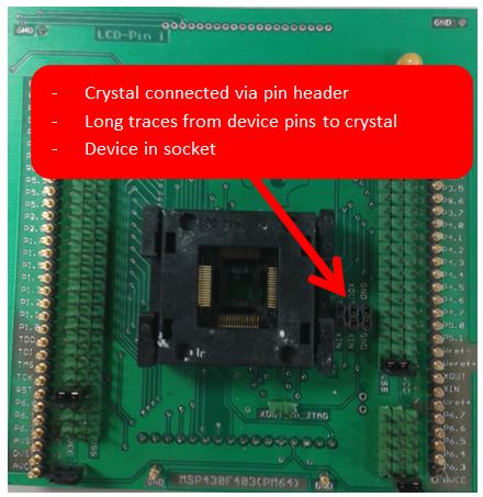
- The nonoptimized board was a lab PCB using socket and a connector to plug in the crystal (see Figure 11). This board added a lot of parasitic capacitance and inductance to the oscillator system.
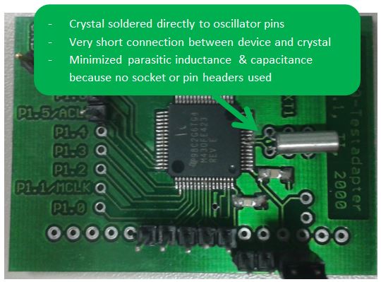
- The optimized board had the MSP device soldered on the PCB and the crystal placed as close as possible to it following the layout guidelines described in this document (see Figure 12). This was done to reduce the negative effect of PCB influence due to bad LFO layout.
 Figure 11. Nonoptimized PCB for General Test Purpose
  Figure 12. PCB Optimized for Low-Frequency Oscillator Measurements
 The results in Table 6 clearly show the positive impact of the XTS toggle sequence to the start-up behavior of the LFO. While all four units had very long start-up times (above 16 s) on the nonoptimized PCB, the start-up time was reduced to approximately 2.3 s on average on an optimized PCB. This example shows that it very important to implement the oscillator fault flag loop before the crystal clock is used by the system to detect possible start-up issues on application level. In addition to the impact of XTS toggling, the results also show the significant impact of the PCB, which was designed according the guidelines in Section 3.
Table 6. Start-up Time Results Demonstrating the Effect of XTS Toggling Using 42-kΩ Crystal
| Unit ID | Start-up Time With 42.4-kΩ Crystal (High ESR) | |||
|---|---|---|---|---|
| Nonoptimized PCB Without XTS Toggling | Nonoptimized PCB With XTS Toggling | Optimized PCB Without XTS Toggling
(seconds) |
Optimized PCB With XTS Toggling
(seconds) |
|
| 1 | No start-up within 16 s | No start-up within 16 s | 3.40 | 0.73 |
| 2 | No start-up within 16 s | No start-up within 16 s | 7.93 | 1.51 |
| 3 | No start-up within 16 s | No start-up within 16 s | 2.62 | 0.78 |
| 4 | No start-up within 16 s | No start-up within 16 s | 2.28 | 0.40 |
As a second experiment, the same measurements were taken using a different crystal with a much lower ESR. The results in Table 7 report the impact of XTS toggling using a low-ESR crystal to the LFO start-up time. The values can be brought down to approximately 1.9 s on average, which is an additional improvement of 0.4 s compared to the results using a 40-kΩ crystal. This clearly shows that the PCB, crystal, and XTS all contribute to a good and acceptable start-up
Table 7. Start-up Time Results Demonstrating the Effect of XTS Toggling Using 14-kΩ Crystal
| Unit ID | Start-up Time With 13.7-kΩ Crystal (Low ESR) | |||
|---|---|---|---|---|
| Nonoptimized PCB Without XTS Toggling | Nonoptimized PCB With XTS Toggling | Optimized PCB Without XTS Toggling
(seconds) |
Optimized PCB With XTS Toggling
(seconds) |
|
| 1 | 2.95 | 0.63 | 1.59 | 0.23 |
| 2 | 4.16 | 0.83 | 2.13 | 0.34 |
| 3 | 2.82 | 0.75 | 1.17 | 0.24 |
| 4 | 2.71 | 0.54 | 1.34 | 0.21 |
In conclusion, the impact of the PCB, humidity, PCB contaminations, and parameters of the used crystal need to be considered when designing an LFO circuit with strict start-up requirements. If the start-up requirements cannot be achieved with the traditional firmware implementation, then the use of the XTS toggling sequence might be an extra option to improve the start-up behavior.