SLAU834 October 2020 ISO7760 , ISO7762 , MSP432E401Y , TPS92520-Q1 , TPS92682-Q1
- Trademarks
- 1Description
- 2Features and Specifications
- 3Schematic, PCB Layout, and Bill of Materials
- 4Software
-
5LEDMCUEVM-132 Power UP and Operation
- 5.1 GUI Start-up
- 5.2 MCU Control Window
- 5.3 SPI Command Window
- 5.4
GUI Devices Window and Example Connections and Power Up
- 5.4.1 TPS92520EVM-133 Connections and Power UP
- 5.4.2 TPS92520EVM-133 Devices Window
- 5.4.3 TPS92518EVM-878 Connections and Power Up
- 5.4.4 TPS92518EVM-878 Devices Window
- 5.4.5 TPS92682EVM-069 + TPS92520EVM-133 Connection and Power UP
- 5.4.6 TPS92520, TPS92682 - LPP074 - E1 Devices Window
- 5.4.7 TPS92682EVM-069 + TPS92520EVM-133 + TPS92662EVM6-901 Connection and Power UP
- 5.4.8 TPS92662EVM6-901 Devices Window
5 LEDMCUEVM-132 Power UP and Operation
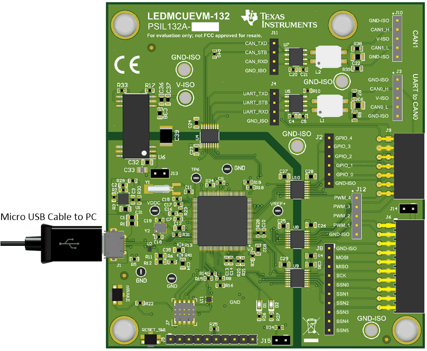
To start the EVM operation, connect the USB cable to the computer and the LEDMCUEVM-132.
 Figure 5-1 LEDMCUEVM-132 Connection to PC Using USB Cable