SLAU834 October 2020 ISO7760 , ISO7762 , MSP432E401Y , TPS92520-Q1 , TPS92682-Q1
- Trademarks
- 1Description
- 2Features and Specifications
- 3Schematic, PCB Layout, and Bill of Materials
- 4Software
-
5LEDMCUEVM-132 Power UP and Operation
- 5.1 GUI Start-up
- 5.2 MCU Control Window
- 5.3 SPI Command Window
- 5.4
GUI Devices Window and Example Connections and Power Up
- 5.4.1 TPS92520EVM-133 Connections and Power UP
- 5.4.2 TPS92520EVM-133 Devices Window
- 5.4.3 TPS92518EVM-878 Connections and Power Up
- 5.4.4 TPS92518EVM-878 Devices Window
- 5.4.5 TPS92682EVM-069 + TPS92520EVM-133 Connection and Power UP
- 5.4.6 TPS92520, TPS92682 - LPP074 - E1 Devices Window
- 5.4.7 TPS92682EVM-069 + TPS92520EVM-133 + TPS92662EVM6-901 Connection and Power UP
- 5.4.8 TPS92662EVM6-901 Devices Window
5.2 MCU Control Window
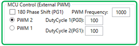
The MCU Control window allows external control of the PWM dimming using the LEDMCUEVM-132 connections to the attached EVM. PWM control is available for each channel with frequency and duty cycle control for frequencies and duty cycles that are not covered by the register settings. It also allows for 180 degree phase shift in between channels if desired. For example, if a PWM signal of 3 kHz was desired, they could use this feature.
 Figure 5-5 MCU Control (External PWM) Window
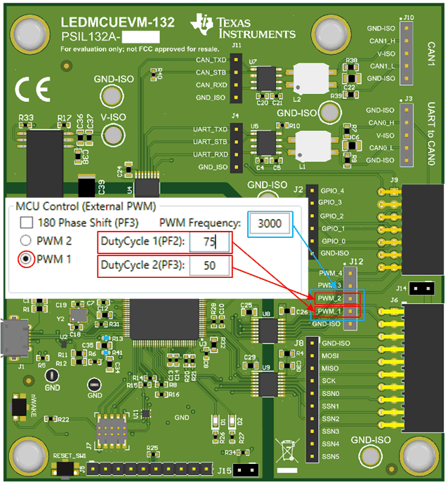
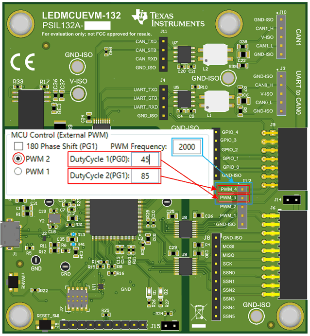
PWM 1 is the first PWM generator from the MCU and controls Duty Cycle 1 at PF2 pin of MCU and Duty Cycle 2 at PF3 pin of the MCU. PMW1-DutyCycle 1 coninsides with PWM_1 on the EVM and PWM1-DutyCycle 2 coninsides with PWM_2 of the EVM, see Figure 5-6. Furthermore, The PWM frequency of PMW 1 generator is the same for both PWM_1 and PWM_2 and is seperate from PWM 2 generator, which controls PWM_3 and PWM_4 on the EVM.
 Figure 5-6 MCU Exnternal PWM for
PWM_1 and PWM_2
 Figure 5-7 MCU Exnternal PWM for PWM_3 and PWM_4