SLVA888C April 2017 – January 2021 TPS65987D , TPS65988
- Trademarks
- 1Schematic Design Guidelines
- 2Layout Guidelines
- 3Summary
- 4References
- A Appendix
- Revision History
A.1 Dead Battery Considerations
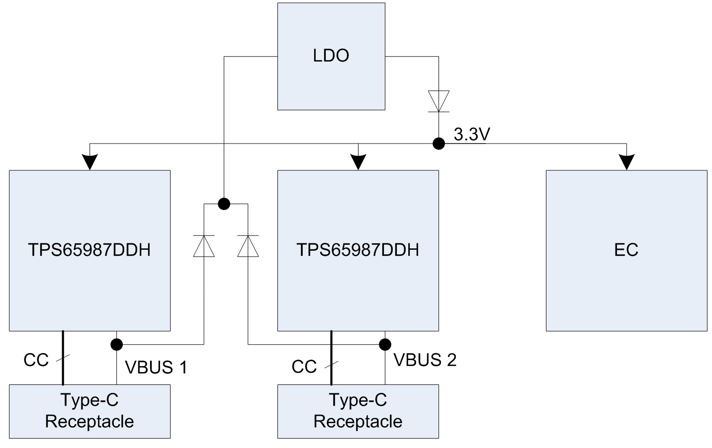
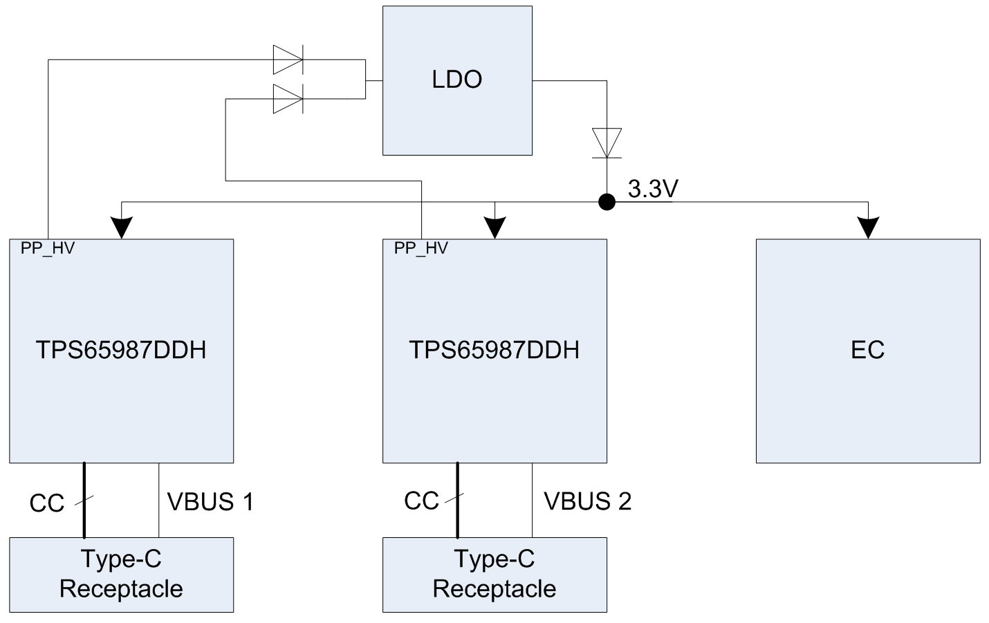
In Dead battery condition, the system power is not available. The whole system must run on the VBUS coming in from the source end. TPS65987DDH has a built in LDO which powers it up. A laptop normally requires an embedded controller (EC) to turn on and manage the PD ports as per the system requirements. When the system supply is not available, there should be an additional regulator sitting from the VBUS or PP_HV/PP_EXT to generate 3.3 V to power up the EC and other critical parts of the system. There are two ways this can be done.
- Using a LDO from VBUS: This device powers up once the VBUS is available and negotiates at least a implicit contract. The VBUS turns on after this and it powers up the LDO which in turn powers up the EC and other required components. This scheme can be used even when the system power comes up only after issuing SRDY command, or BUZPOWERZ configuration is such that the power path is not turned on until instructed by EC.
 Figure 5-1 Using an LDO from VBUS
 - Using a LDO from
PP_HV/PP_EXT of the PD controller: In this mode, this device turns on from
its built in LDO. It negotiates a contract and turns on the power FETs. The
moment the FETs are on, they power up the LDO which powers all other
required components.
 Figure 5-2 Using an LDO from
PP_HV/PP_EXT