SPRUIY9B May 2021 – October 2023
- 1
- Abstract
- Trademarks
- 1Key Features
- 2EVM Revisions and Assembly Variants
- 3Important Usage Notes
-
4System Description
- 4.1 Key Features
- 4.2 Functional Block Diagram
- 4.3 Power-On/Off Procedures
- 4.4
Peripheral and Major Component
Description
- 4.4.1 Clocking
- 4.4.2 Reset
- 4.4.3 Power
- 4.4.4 Configuration
- 4.4.5 JTAG
- 4.4.6 Test Automation
- 4.4.7 UART Interface
- 4.4.8 Memory Interfaces
- 4.4.9 Ethernet Interface
- 4.4.10 USB 3.0 Interface
- 4.4.11 PRU Connector
- 4.4.12 User Expansion Connector
- 4.4.13 MCU Connector
- 4.4.14 Interrupt
- 4.4.15 I2C Interface
- 4.4.16 IO Expander (GPIOs)
-
5Known Issues
- 5.1 Issue 1: LP8733x Max output Capacitance Spec Exceeded on LDO0 and LDO1
- 5.2 Issue 2: LP8733x Output Voltage of 0.9V Exceeds AM64x VDDR_CORE max Voltage Spec of 0.895 V
- 5.3 Issue 3 - SDIO Devices on MMC0 Require Careful Trace Lengths to Meet Interface Timing Requirements
- 5.4 Issue 4 - LPDDR4 Data Rate Limitation in Stressful Conditions
- 5.5 Issue 5 - Junk Character
- 5.6 Issue 6 - Test Power Down Signal Floating
- 5.7 Issue 7 - uSD Boot Not Working
- 6Regulatory Compliance
- 7Revision History
Abstract
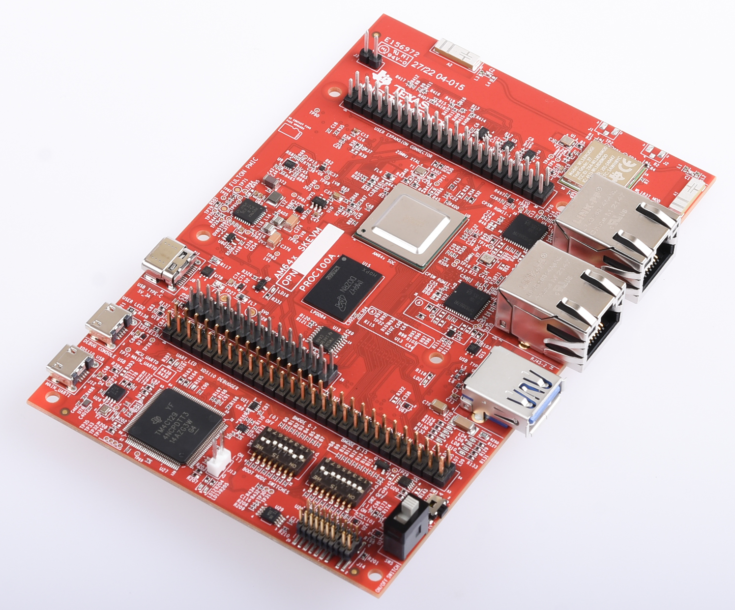
This technical user’s guide describes the hardware architecture of the AM64x SKEVM. The AM64x processor comprises of a Dual-Core 64-bit Arm-Cortex A53 microprocessor, 2x Dual core Arm® Cortex®-R5F MCUs and an Arm Cortex-M4F MCU.
The AM64x starter kit is a stand-alone test and development platform that is an excellent choice for accelerating the prototype phase of the next design. The kit includes: wired and wireless connectivity, three expansion headers, multiple boot options and flexible debug capabilities.
The starter kit is equipped with AM64x processor from TI and an optimized feature-set to allow the user to create commercial and industrial devices using Ethernet-based, USB, and serial wired interfaces plus 2.4-GHz and 5-GHz wireless communications. Two 1-Gbps Ethernet Ports for wired connectivity are on-board, in addition to three expansion headers (PRU, MCU, User) headers to expand the functionality of the board. Using standard serial protocols such as UART, I2C, and SPI, the starter kit can interface with a multitude of other devices, acting as a communications gateway. Receiving 5-V power from a standard USB-C port, the starter kit allows the user to access the R5F cores of the AM64x; making the device an excellent choice as a programmable logic controller (PLC) or motor controller, processing sensor inputs and managing peripherals in real-time while running Linux on the A53 cores, and making the device the central engine in a remote industrial communication network. The embedded emulation logic allows for emulation and debugging using standard development tools such as Code Composer Studio™ from TI.