SBAA548A April 2022 – May 2022 ADS8588S , ADS8681 , ADS8686S , ADS8688 , ADS8688A
3.2 Electrostatic Discharge (ESD)
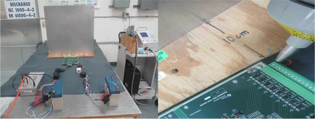
The IEC 61000-4-2 standard specifies the details for ESD test including the test criterion and setup requirements. The main purpose of IEC 61000-4-2 test is to determine the immunity of EUT to external ESD events during operation. Figure 3-3 shows the diagram of the setup and connection for the ESD test. A 0.8-m high wood table stands on the GRP ground. A 1.6 m × 0.8 m horizontal coupling plane (HCP) is placed on the table. The EUT is tested and isolated on a 0.5-mm thick insulating mat that is placed on top of the HCP. The EUT is placed 0.1-m away from the vertical coupling plane (VCP) which has 0.5 m × 0.5 m dimensions and is placed on the insulating mat.
There are two types of ESD tests: contact discharge and air discharge. The contact discharge test is the most aggressive direct discharge test and the tip of the ESD gun is placed to conductive screws of the input terminal blocks (J1 and J2) on the ADS8686S EMC test board. Air discharge tests are run three different ways: direct air gap discharge, indirect discharge to the horizontal coupling plane (HCP), and vertical coupling plane (VCP). In the air gap discharge test, the tip of the ESD gun is placed near insulating surfaces of the input terminal blocks (J1 and J2) on the ADS8686S EMC test board. In the discharge test to the HCP and VCP, the ESD signal is discharged into a nearby conductive plane, representing an ESD strike onto the rack of equipment the design is mounted in. Figure 3-4 shows a zoomed-in view where the ESD strikes are applied. The discharges to the HCP and the VCP are individually done with the ESD gun 1 and the ESD gun 2 in the contact discharge mode. The ESD gun is held in the plane of the coupling plane and perpendicular to edge, then the ESD strikes are discharged into the edge of the plane.
Figure 3-5 shows a photograph of the actual setup for the ESD test.
 Figure 3-5 Photograph of Laboratory Setup for ESD Test
For the ESD test, the EUT is tested with at least 20 discharges at each rating, 10 discharges each at a positive and negative polarity. Table 3-2 shows the results of the ESD test.
| Test | IEC Standard | Type | Test Voltage | Test Level | Criterion | Test Result |
|---|---|---|---|---|---|---|
ESD | IEC 61000-4-2 | Contact Discharge | +8 kV | 4 | A | Pass |
–8 kV | A | Pass | ||||
Air Discharge | +15 kV | 4 | A | Pass | ||
–15 kV | A | Pass |