SBAA548A April 2022 – May 2022 ADS8588S , ADS8681 , ADS8686S , ADS8688 , ADS8688A
3.6 Radiated Emissions (RE)
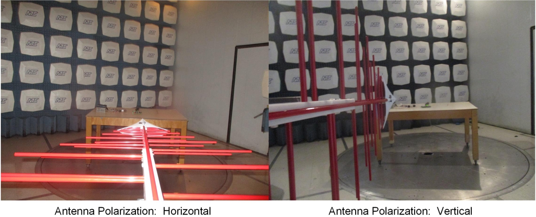
The CISPR 11 standard defines requirements, test procedures, and limits for radiated disturbances from industrial, scientific, and medical (ISM) equipment. The purpose of this test is to measure and evaluate the radiated emissions that are generated by the EUT. The test is performed in a semi-anechoic chamber and the EUT is placed on a nonconductive table at 0.8-m height. The table with the EUT is intended to be rotated from 0° to 360° to find the direction of maximum radiated emission. The height of the receiving antenna is varied between 1 m and 4 m to find the maximum field strength. The measurement distance between the EUT and the receiving antenna is 3 m. An alternative measurement distance is 10 m, which has a different limit. The EUT is scanned in the frequency band between 30 MHz and 1 GHz. The radiation from the EUT is received by the receiving antenna, which is set to a horizontal or vertical polarization position for each testing. The signal from the antenna is connected to the input of an EMI test receiver and spectrum analyzer for signal acquisition and analysis with a specified resolution bandwidth and detector type. A pre-amplifier can be used if necessary. The test system for the EUT is configured in quasi peak detection mode, which is effectively weighed by the repetition rate of energy in the band.
Table 3-6 shows the CISPR 11 quasi - peak (QP) limits for Group 1 ISM equipment which includes all ISM equipment that uses RF energy only for internal functioning of the equipment.
| Frequency Range (MHz) | 3-m Distance | 10-m Distance | ||
|---|---|---|---|---|
| Class A (dBμV/m) | Class B (dBμV/m) | Class A (dBμV/m) | Class B (dBμV/m) | |
| 30–230 | 50.5 | 40.5 | 40 | 30 |
| 230–1000 | 57.5 | 47.5 | 47 | 37 |
Figure 3-12 plots the relevant limit lines for Class A and Class B at 3-m and 10-m distance between the antenna and EUT when using a QP detector.
The industrial systems designed with ADS8686S usually belong to Class A Group 1 equipment category. The measurement distance between the ADS8686S EUT and the receiving antenna is 3 m.
Figure 3-14 shows a photograph of the actual setup for the radiated emission test.
 Figure 3-14 Photograph of Laboratory Setup for Radiated Emission Test
Figure 3-15, Figure 3-16, and Figure 3-17 show measured radiated emissions from the ADS8686S EMC test board with the PHI controller card at different serial clock (SCLK) frequencies and sampling rates.