SBAA548A April 2022 – May 2022 ADS8588S , ADS8681 , ADS8686S , ADS8688 , ADS8688A , ADS8688W
3.3 Surge Immunity (SI)
The IEC 61000-4-5 standard details the test equipment and procedures for performing surge testing at a specific source impedance and coupling mode (line-to-line or line-to-ground). The test is to verify the EUT immunity on both power and data lines to high-energy surges caused by switching of power systems from load changes and short circuit faults, direct or indirect lighting strikes. The IEC 61000-4-5 specifies two types of combination wave generators (CWGs). The 10 μs / 700 μs CWG is specifically used to test the ports of symmetrical telecommunication lines. The 1.2 μs / 50 μs CWG is used for all other cases. The surge for all other cases combines a 1.2 μs / 50 μs (1.2-μs rising time with 50-μs pulse width) open-circuit voltage waveform and 8 μs / 20 μs (8-μs rising time with 20-μs pulse width) short-circuit current waveform. The EUT is subject to 5 positive and 5 negative surges at each rating. The surge is repeated at least once per minute. A coupling and decoupling network (CDN) is required by the surge test. The IEC 61000-4-5 defines the impedance and capacitance used in the coupling network in different cases. The EUT is tested with the surge through a coupling and decoupling network (CDN117) with a 0.5-μF capacitor and a twisted cable.
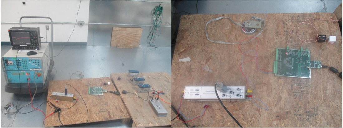
Figure 3-7 shows a photograph of the actual setup for the surge test. An oscilloscope is intended to monitor the output signal from surge signal generator during testing.
 Figure 3-7 Photograph of Laboratory Setup for Surge Test
Table 3-3 shows the results of the surge test.
| Test | Standard | Type | Impedance | Test Voltage | Test Level | Criterion | Test Result |
|---|---|---|---|---|---|---|---|
| Surge | IEC 61000-4-5 | Line-to-Line | 42 Ω (2-Ω source impedance + 40 Ω from coupling network) | 500 V | 1 | A | Pass |
| Line-to-Ground | 42 Ω (2-Ω source impedance + 40 Ω from coupling network) | B | Pass | ||||
| Line-to-Line | 42 Ω (2-Ω source impedance + 40 Ω from coupling network) | 1 kV | 2 | A | Pass | ||
| 2-Ω source impedance only(1) | B | Pass | |||||
| Line-to-Ground | 42 Ω (2-Ω source impedance + 40 Ω from coupling network) | B | Pass | ||||
| 2-Ω source impedance only(1) | B | Pass |