SNVA856B May 2020 – October 2022 LM63615-Q1 , LM63625-Q1 , LM63635-Q1 , LMR33620 , LMR33620-Q1 , LMR33630 , LMR33630-Q1 , LMR33640 , LMR36006 , LMR36015 , TPS54360B , TPS54560B
- Working With Inverting Buck-Boost Converters
- Trademarks
- 1 Introduction
- 2 Inverting Buck-Boost Converter
- 3 Basic Operation
- 4 Operating Considerations of a Buck Based Inverting Buck-Boost
- 5 Component Selection for the IBB
- 6 General Considerations
- 7 Auxiliary Functions
- 8 Design Examples
- 9 Summary
- 10References
- 11Revision History
4.2 Current Stress
The inductor currents and peak switch currents in the IBB are larger than in the equivalent buck converter from which it is made. First, the average input supply current can be calculated as for any converter, using Equation 3.

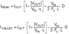
Notice that when the magnitude of the output voltage is less than the input voltage (buck mode), the input current is less than the output current. This is the same as for an ordinary buck. However, when the output voltage is greater than the input voltage (boost mode), the input current is greater than the output current. This is the same as for an ordinary boost converter. Another thing to note is that the efficiency of the IBB is somewhat less than an equivalent buck or boost; this is discussed further on. The average inductor current is the sum of the input and output currents, and is given by Equation 4. The peak and valley of the inductor current are given in Equation 5. The first term in Equation 5 is the average inductor current, while the second terms represent the inductor ripple current. Since the peak and valley of the inductor current pass through the MOSFET power switches, they determine how much output current a given IBB can supply, when built from a buck. Most buck regulators are rated for a certain maximum load current. This is convenient since the load current and average inductor current are the same for a buck. However, as seen from Equation 4 the average inductor current for an IBB is always greater than the load current. Therefore, choose a buck regulator with a greater maximum load current when using it as an IBB.


The peak and/or valley current limit of the converter dictate the maximum inductor current and therefore the maximum load current that can be supplied. Equation 5 can be modified to a slightly more user friendly form, and used to help choose a buck regulator that has enough current capability to be used in a given IBB application. If we choose a typical value for the inductor current ripple (ΔIL) as 30% of the output current, then we can use Equation 6 to determine the peak and valley of the inductor current for a given application. As an example, suppose we need to convert +12 V to –5 V at a load current of 2 A. Using ΔIL = 0.6 A and an efficiency of 0.85, in Equation 6, we find an IPEAK of 3.28 A and an IVALLEY of 2.68 A. A regulator such as the LMR33630 has a peak current limit of 3.85 A (minimum) and a valley current limit of 2.9 A (minimum). Since our peak and valley currents are less than the peak and valley current limits of the device, this regulator is suitable for the application. A device such as the LMR14030 uses peak current limit only, with a minimum specification of 4.5 A. This regulator would also be a good candidate. Notice that these are all "3-A" regulators, even though we only need 2 A of load current in our example. A "2-A" regulator such as the LMR33620 having peak and valley current limits of 2.9 A (minimum) and 1.95 A (minimum) would not work. Note that the worst case for calculating the current occurs at the minimum input voltage and/or when the IBB is boosting.
