SPRAC76G November 2022 – February 2024 AM5706 , AM5708 , AM5716 , AM5718 , AM5726 , AM5728 , AM5729 , AM5746 , AM5748 , AM5749 , AM620-Q1 , AM623 , AM625 , AM625-Q1 , AM625SIP , AM6411 , AM6412 , AM6421 , AM6422 , AM6441 , AM6442 , AM6526 , AM6528 , AM6546 , AM6548
- 1
- Sitara Processor Power Distribution Networks: Implementation and Analysis
- Trademarks
- 1Introduction
- 2Guidelines for PCB Stack-Up
- 3Physical Layout Optimization of the PDN
- 4Static PDN Analysis (IR Drop Optimization)
- 5Dynamic Analysis of PCB PDN
- 6Checklist for PDN
- 7Implementation Examples and PDN Targets
- Revision History
5.1 Selecting Decoupling Capacitors to Meet ZTARGET
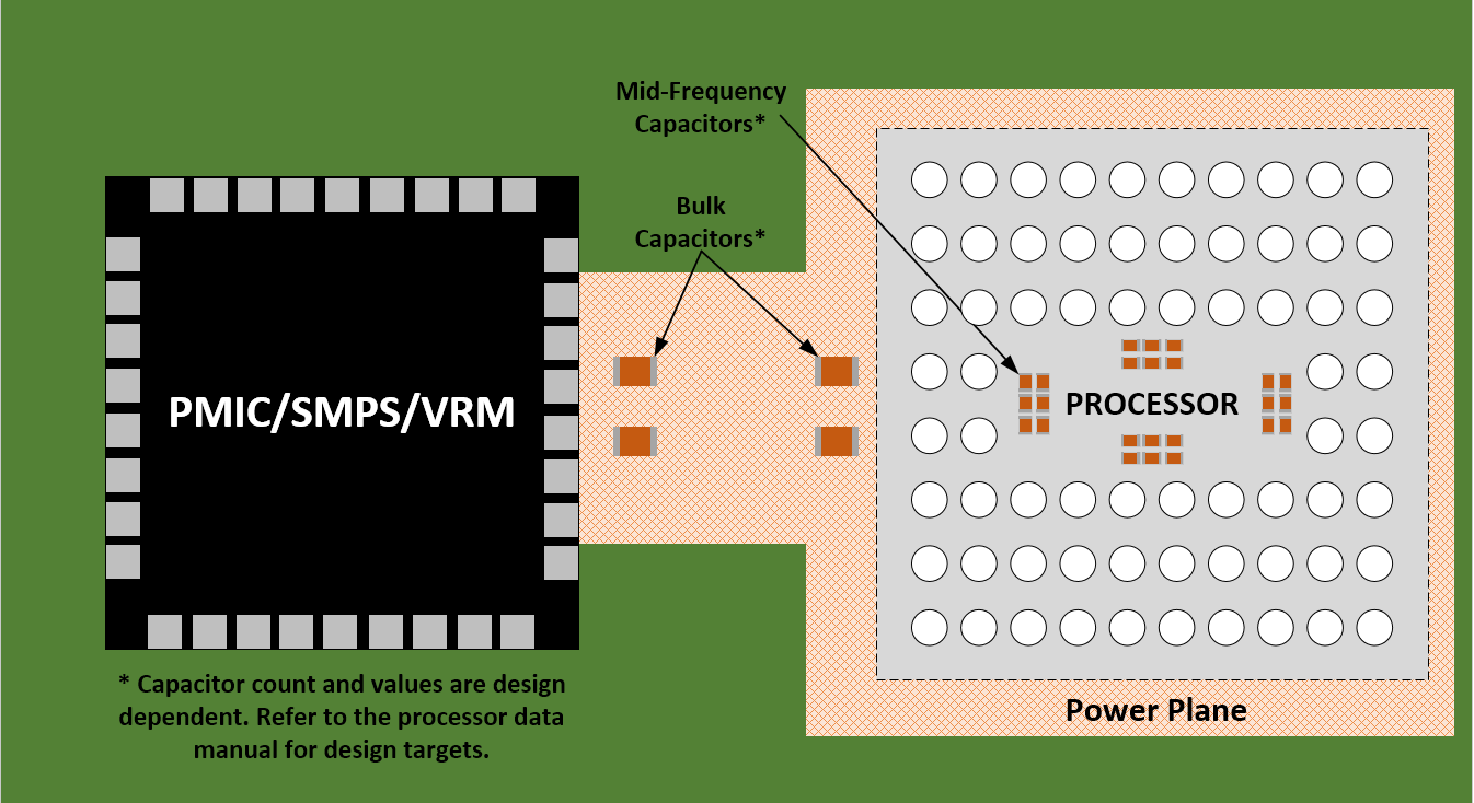
To maintain power integrity throughout the entire frequency range of interest, the power distribution network relies on the voltage regulator module (VRM/SMPS), the on-board discrete bulk electrolytic and ceramic decoupling capacitors, and the inter-plane capacitances (capacitance from the power-ground sandwich in the board stack-up). For a first-order analysis, the VRM of the power management integrated circuit (PMIC) can be modeled as a series-connected resistor and inductor. A PMIC, at low frequencies (up to 500 KHz-1 MHz), typically has low impedance and is capable of responding to the instantaneous requirements of the processor. The ESR and ESL values for the VRM are therefore very low. Beyond lower frequencies, the VRM impedance is primarily inductive, making it incapable of meeting the transient current requirement of the device. The bulk and ceramic discrete decoupling capacitors must provide the required low impedance from the point at which the VRM becomes inductive. The effectiveness of the bulk and mid-frequency decoupling capacitors (1 MHz-70 MHz, depending on the capacitor’s ESL and ESR) is limited by its placement (due to loop inductance), value, and type. Refer to Figure 5-3 for a capacitor placement example. Note that in order to minimize the loop inductance, the mid-frequency capacitors have been placed directly underneath the processor (on the bottom side of the PCB).
 Figure 5-3 Example Capacitor
Placement
Figure 5-3 Example Capacitor
PlacementThe bulk capacitors should be located near the point of entry of the supply entrance to the board. The decoupling capacitors maintain the PDN impedance at the required value beyond the VRM frequency and until the frequency at which mid-frequency capacitors become useful. The mid-frequency SMT capacitors are useful in the 10 to 150 MHz range and higher. These capacitors are primarily ceramic capacitors that come in several dielectric types (NPO, X7R, X5R, and Y5V) and several sizes (1206, 0805, 0603, 0402, and so forth). The mid-frequency capacitors are much smaller than the bulk capacitors and can be placed closer to the transistor circuit. Since the ceramic capacitors are smaller, they have lower ESR and ESL and lower capacitance than bulk capacitors, leading to a higher resonance frequency with smaller impedance at resonance. Therefore, ceramic capacitors can be used at higher frequencies. Typical mid-frequency capacitors have capacitance in the range of 1 nF –100 nF, ESR in the range of 10-100 mΩ, and ESL in the range of 0.5 nH – 1 nH.
The concept of “loop inductance” is a useful metric for quantifying the effectiveness of the decoupling capacitors of a power distribution network. To calculate the “loop inductance” associated with decoupling capacitor placement, Equation 4 can be used:

Where Leff is the effective loop inductance, Z ( power, GND pads of decap) represents the Z-parameters of the port defined across the power and ground pads of the corresponding decap. The frequency should be chosen in the “flat” region of the Z-parameter response, typically in the 50 MHz – 70 MHz range.