SPRACR6 April 2020 F29H850TU , F29H859TU-Q1 , TMS320F280023-Q1 , TMS320F280023C , TMS320F280025C , TMS320F280025C-Q1 , TMS320F280041-Q1 , TMS320F280041C , TMS320F280041C-Q1 , TMS320F280048-Q1 , TMS320F280048C-Q1 , TMS320F280049-Q1 , TMS320F280049C , TMS320F280049C-Q1 , TMS320F28384D , TMS320F28384D-Q1 , TMS320F28384S , TMS320F28384S-Q1 , TMS320F28386D , TMS320F28386D-Q1 , TMS320F28386S , TMS320F28386S-Q1 , TMS320F28388D , TMS320F28388S , TMS320F28P650DH , TMS320F28P650DK , TMS320F28P650SH , TMS320F28P650SK , TMS320F28P659DH-Q1 , TMS320F28P659DK-Q1 , TMS320F28P659SH-Q1
4 C2000 Controller Configuration for DPCA DC/AC System
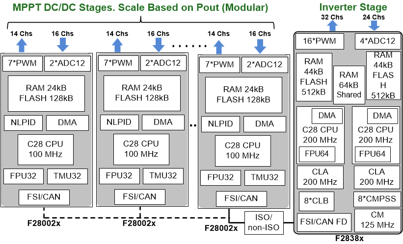
This section discusses different C2000 MCU configuration for distributed power control of the solar string inverter DC/AC system. Use of the fast communication link such that the FSI port in order to significantly increase the scalability of MCU resources (PWM, ADC and MIPs) and hence, implementing the DPCA system will also be discussed. Figure 12 illustrates the use of two different series of C2000 MCUs in order to implement DPCA for the solar string inverter system discussed before. As indicated in Figure 12 one F2838x series MCU is used for grid-tie inverter control and multiple F28002x series MCUs are used for MPPT DC/DC control. All the MCUs are then connected through the FSI port. This configuration will allow full flexibility and scalability in the design. For example as indicated in Table 1, one inverter system may require 12 MPPT DC/DC stages which can be implemented with four F28002x MCUs controlling the DC/DC stages and one F2838x MCU controlling the DC/AC stage. Then all the MCUs can be connected over the FSI ports. Now this can be very efficiently modified for another inverter system requiring 16 MPPT DC/DC stages just by adding one more F28002x in the system. The max number of F28002x MCUs that can be connected through FSI and the way the MCUs are connected in such system is further discussed in Section 5.
 Figure 12. F28002x and F2838x MCU Configuration for DPCA Solar Inverter System
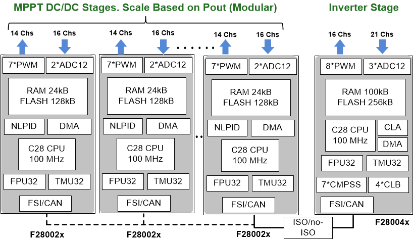
 Based on the application requirements, the inverter stage controller in Figure 12 can also use F28004x series MCU, which is indicated in Figure 13. All the MCUs are then connected through the FSI port. Again, the maximum number of F28002x MCUs that can be connected through FSI and the way they are connected in such system is further discussed in Section 5.
 Figure 13. F28002x and F28004x MCU Configuration for DPCA Solar Inverter System
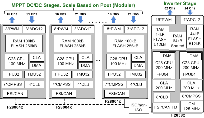
 If the MPPT DC/DC stages require more peripheral resources, then these can be controlled by F28004x series MCUs with one F2838x MCU controlling the inverter stage, which is illustrated in Figure 14.
 Figure 14. F28004x and F2838x MCU Configuration for DPCA Solar Inverter System