SPRACR6 April 2020 F29H850TU , F29H859TU-Q1 , TMS320F280023-Q1 , TMS320F280023C , TMS320F280025C , TMS320F280025C-Q1 , TMS320F280041-Q1 , TMS320F280041C , TMS320F280041C-Q1 , TMS320F280048-Q1 , TMS320F280048C-Q1 , TMS320F280049-Q1 , TMS320F280049C , TMS320F280049C-Q1 , TMS320F28384D , TMS320F28384D-Q1 , TMS320F28384S , TMS320F28384S-Q1 , TMS320F28386D , TMS320F28386D-Q1 , TMS320F28386S , TMS320F28386S-Q1 , TMS320F28388D , TMS320F28388S , TMS320F28P650DH , TMS320F28P650DK , TMS320F28P650SH , TMS320F28P650SK , TMS320F28P659DH-Q1 , TMS320F28P659DK-Q1 , TMS320F28P659SH-Q1
2.2 Distributed Power Control Architecture – AC/DC System
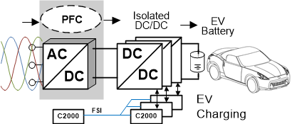
Figure 3 illustrates the DPCA configuration for a fast DC charging application for electric vehicle (EV). Most of the modern off-board fast chargers have a power rating of 50 kW to 135 kW which allows battery recharging in less than 30 minutes. New 150 kW fast chargers have also been announced with 350 kW chargers as a part of long-term plan. These commercially available fast chargers are powered from 208/480 V three phase input. This is implemented with a 3 phase PFC, such as a Vienna PFC, followed by a DC/DC as illustrated in Figure 3. The DC/DC converter, usually a resonant topology, provides an efficient means of interfacing the output DC bus voltage from a three phase Vienna rectifier/T-type rectifier to the battery of an electric vehicle. The phase-shifted full-bridge topology with the SiC devices also constitutes an alternative solution for the DC/DC stage. A single C2000 MCU could be used to control the Vienna PFC and single or multiple C2000 MCUs could control multiple DC/DC stages. Then, all the MCUs could be connected through the FSI ports for overall system management. For more details on C2000 MCU-based Vienna PFC and EV charging DC/DC control, see the Vienna Rectifier-Based, Three-Phase Power Factor Correction (PFC) Reference Design Using C2000™ MCU and the Bidirectional CLLLC Resonant Dual Active Bridge (DAB) Reference Design for HEV/EV Onboard Charger, respectively.
 Figure 3. Fast DC Charger for EV in a DPCA Configuration
 The fast DC charging system illustrated in Figure 3 shows some limitation in high power EV charging applications. When implemented this way the overall system efficiency, including the service transformer (that provides the 208/480Vac input), is very low (about 93%). In addition to this, the overall size, weight and the installation cost of such a system is very high when the power rating is high to enable fast charging.
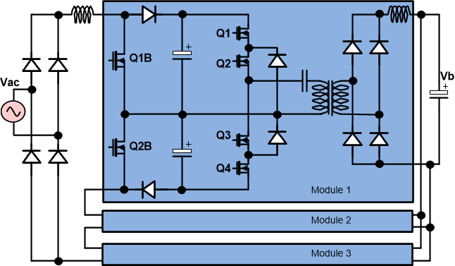
An alternative approach is to use Solid-State Transformer [3] (SST) technology to directly connect the fast charger to the 2.4 kV Medium-Voltage (MV) single-phase line. This avoids the use of service transformer, improves efficiency and significantly reduces the installation costs. However, due to the relatively high voltage (2.4 kV ac) at the converter input, a modular design approach needs to be adopted if commercially available Silicon Carbide (SiC) devices are to be used. One example is the Multi-Cell Boost (MCB) topology with three input-series-output-parallel (ISOP) connected dc/dc converter modules as shown in Figure 4. This is adopted for the fast charger application due to its high power density, high efficiency, low cost, low number of switches and expected high reliability.
 Figure 4. Input-Series-Output-Parallel Multi-Cell dc/dc for fast EV Charger
 By using this topology, the losses can be reduced significantly compared to the state-of-the-art solution with low-frequency transformer and three-phase PWM rectifier as shown in Figure 3. This topology has additional advantages such as independent control of input and output stages, a relatively simple control strategy for dc bus capacitor voltage balancing and the reduction of the input and output inductors by interleaving the 3-level boost converters at the input side and the NPC converters at the output side. The ISOP configuration of the adopted MCB topology modules enables scalability in both the input voltage and the output power ratings. Here again, based on the power level of the fast charger and its input voltage ratings, the ISOP configuration could consists of multiple power stages controlled by multiple C2000 MCUs and then the MCUs can be connected through the high speed FSI ports to form a fast EV charging DPCA system.
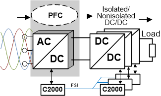
Figure 5 shows the isolated/non-isolated off-line AC/DC DPCA system where the input AC voltage is rectified through a PFC stage and then applied to the high frequency isolated DC/DC converter. The PFC stage draws sinusoidal input current in phase with the input voltage in order to maintain high power factor (PF) and low THD input current and provides a regulated high voltage DC output to the DC/DC stage. The DC/DC stage generates an isolated low voltage DC output with tight regulation and fast transient response against fluctuations in input voltage and output load current. Such AC/DC system is usually controlled by single or dual C2000 MCUs. However for higher power level both the power conversion stages could consist of multiple converters controlled by multiple C2000 MCUs. All the MCUs can then be connected through the high speed FSI port for overall system management.
 Figure 5. Off-Line AC/DC Power Supply in a DPCA Configuration