TIDUDJ6B August 2022 – February 2023 OPA388-Q1
- Description
- Resources
- Features
- Applications
- 5
- 1System Description
- 2System Overview
- 3Hardware, Testing Requirements, and Test Results
- 4Design Files
- 5Software Files
- 6Related Documentation
- 7Trademarks
- 8Revision History
1 System Description
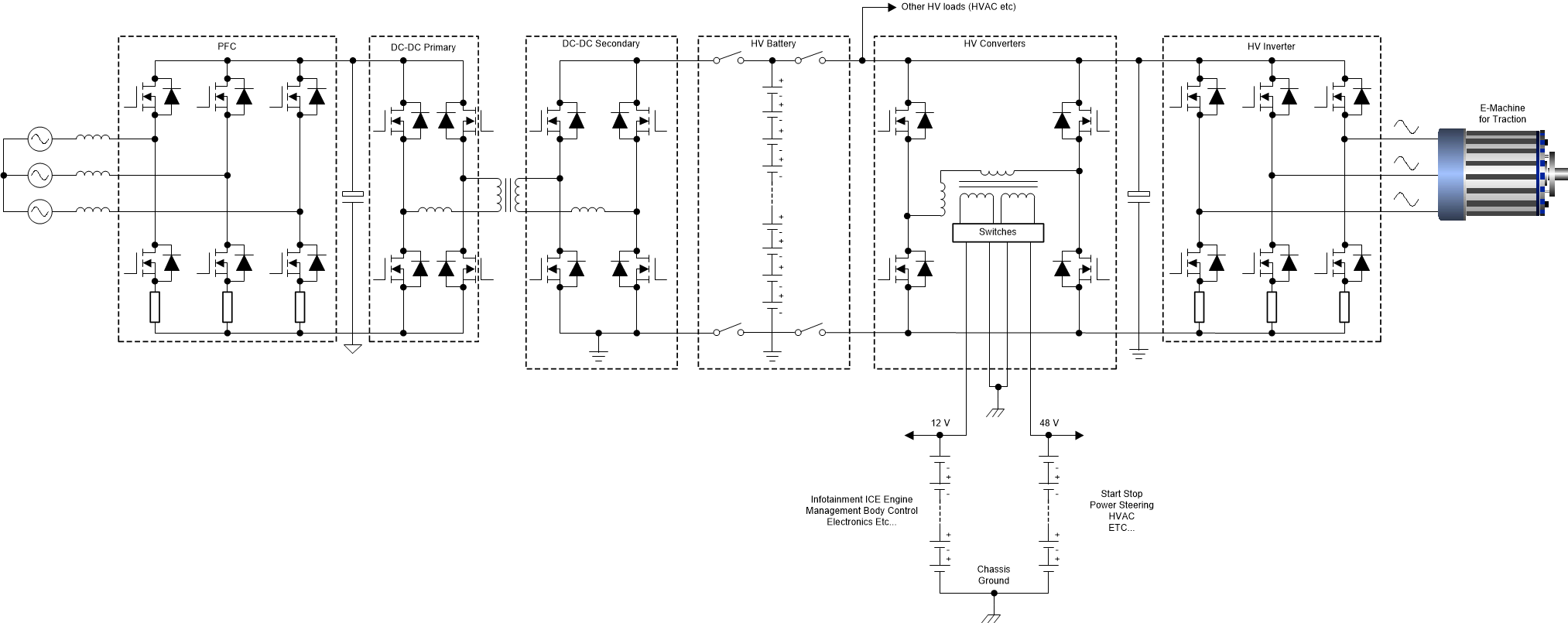
In response to the latest changes in global environmental conditions and to reduce greenhouse gases, there is a need to have hybrid or electric traction units, which have very low or zero emissions. In a hybrid electric vehicle (HEV) or electric vehicle (EV), high-voltage batteries are used as storage elements to power the wheels. High-voltage batteries for automotive systems are defined as those with ≥ 60 V. Onboard chargers or external DC converters are used to source the power. Meanwhile, high-voltage batteries are used to store that energy. DC/DC converters and motor control inverters are used to power the wheels and other subsystems such as heating, ventilating, and air conditioning (HVAC). All these subsystems are working on high voltage.
 Figure 1-1 Typical HEV / EV Power
Train
Figure 1-1 Typical HEV / EV Power
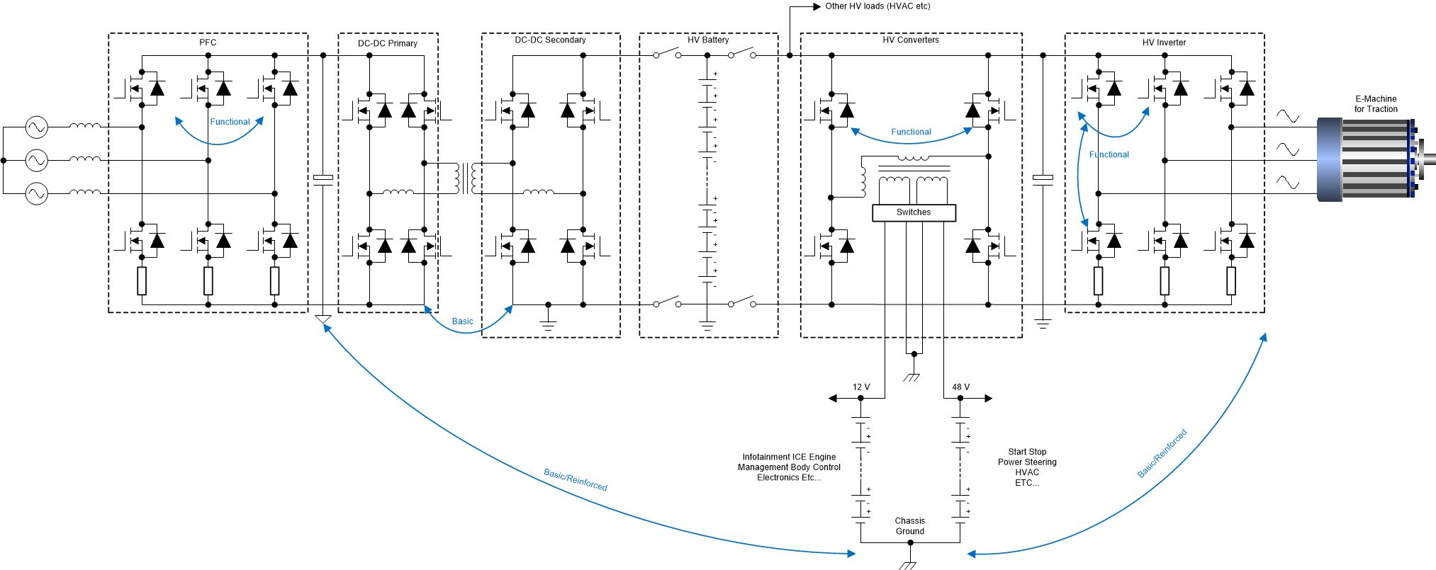
TrainHigh-voltage components in HEV or EV systems are typically isolated from the chassis for functional and occupant safety reasons. The level of isolation in systems completely depends on the application, subsystem location within the vehicle, and the effective peak operating voltage. In general, HEVs and EVs use functional, basic, and reinforced isolation-based devices (see #T5081059-4). Functional isolation is used for protecting ground loops and the operation of those devices. Basic isolation is a single level of isolation which provides basic protection against electric shock. Reinforced isolation is a double level of isolation which provides higher protection against electric shock. Automotive power-train system developers should select basic or reinforced isolated components based on the voltage of the battery and peak voltages of the onboard charger and inverter.
 Figure 1-2 Isolation in HEV/EV
Isolation is a critical parameter for the safety of HEV and EV systems. Due to many factors such as improper motor winding, deteriorating wiring harnesses, general aging, and power dissipation, the operating temperature and peak electrical stress on semiconductors may lead to degradation or loss of isolation in these HEV and EV systems. Any single point for failure of isolation loss does not have much impact on the operation of the system, but it does become a potential life risk when operators make contact with this high-voltage operating environment. Vehicle manufacturers need to have a mechanism to detect every single point failure of isolation in a complete system and have a necessary preventive action in place. Measure isolation resistance and insulation leakage currents to check the safety of occupants in the HEV or EV system. As per FMVSS 305 specification, at least 500 Ω/V of isolation resistance must be maintained from high-voltage systems to chassis ground. Depending on the leakage current measured, HEV/EV system error-handling functions may be designed to take appropriate actions.. Functions or systems will be built to disconnect high-voltage relays and discharge the DC-link capacitors.
Checking the leakage or low ohmic resistance paths from high-voltage nets to the low-voltage chassis ground is important. The necessary isolation resistance is calculated based on battery voltage, creating a isolation breakage path and monitoring the deflections as explained in this design guide. Based on the vehicle architecture, the number of sampling points for isolation leakage measurements varies.