TIDUDJ6B August 2022 – February 2023 OPA388-Q1
- Description
- Resources
- Features
- Applications
- 5
- 1System Description
- 2System Overview
- 3Hardware, Testing Requirements, and Test Results
- 4Design Files
- 5Software Files
- 6Related Documentation
- 7Trademarks
- 8Revision History
3.1 Required Hardware
Hardware that measures isolation resistance is built with a high-voltage measurement circuit and isolation breaking circuit. As previous sections have explained, isolation measuring and a high-voltage monitoring circuit is implemented in the schematics and printed-circuit board (PCB). Use the OPA2348-Q1 and OPA320-Q1 op amps to reduce the error in high-voltage leakage current and voltage measurements.
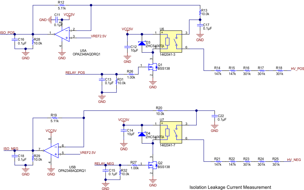
As #ID-716AD4C3-F3B2-4B8A-D06C-2261D5F9E286 shows, MELF resistors R14, R15, R16, R17, and R18 are used for a potential divider circuit for the high-voltage positive line, whereas R21, R22, R23, R24, and R25 are used for a potential divider circuit for the high-voltage line. C17 and C22 are placed only in the schematic and layout to filter relay switching noise. These capacitors are not used in performance testings because they are a potential weak link for performance and reliability in mass production. MELF resistors are chosen to have less tolerance, high reliability, and a low temperature coefficient of resistance (TCR). Any deviation in resistor values have an impact on the error of interlock leakage current calculations.
 Figure 3-1 Leakage Current Measurement
R12 and R19 are chosen based on the battery voltage and signal range of isolation leakage current. Because the resistance and power dissipation is low, there is a possibility to select a high-precision resistance to calculate accurate leakage current. The OPA2348-Q1 is used for U5A and U5B, which support the voltage measurement with an applied offset given by VREF2.5V. The ISO POS and ISO NEG voltage change based on the state of battery voltage and the state of U6 and U7 relays. Q1 and Q2 are small signal transistors to control the relays. D3 and D4 are freewheeling diodes for relay coils (see #ID-5E0A904A-5010-4FFF-9F82-B190E59FC09C).
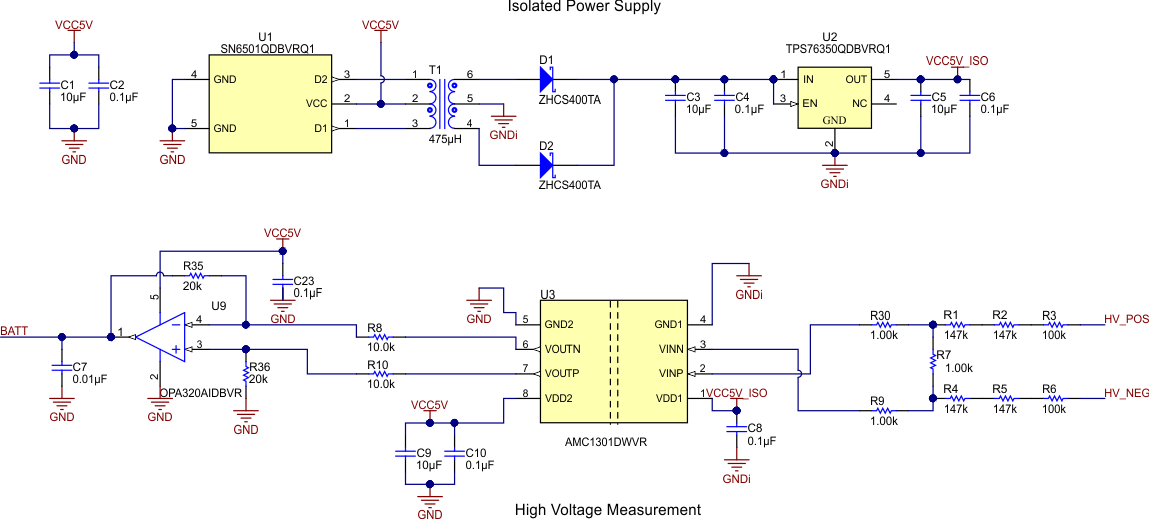
 Figure 3-2 High-Voltage Measurement and Iso Power
Isolated power is required for isolated high-voltage measurements with the AMC1301-Q1 or AMC1311-Q1. The SN6501-Q1 transformer driver is used to transfer the power from T1 primary to secondary. D1 and D2 are used to rectify the power on the secondary side of the transformer. Based on turns ratio and operation of the SN6501-Q1, the output of D1 and D2 will be in the range of 6.2 V to 7 V. The TPS76350-Q1 device is used to regulate the output voltage to 5 V.
VCC5V_ISO is used to supply the secondary side of the AMC1301-Q1 device (see #ID-A3F73708-5BE3-41D8-D6D0-EFD0C9FA042F). GNDi is completely floating in the high-voltage power line. R1, R2, R3, R4, R5, and R6 are the MELF resistors used for the potential divider. R7 is the shunt resistor for voltage measurement. Selecting R7 heavily depends on the input measurement range of the AMC1301-Q1 device (250 mV) and voltage range of the battery.
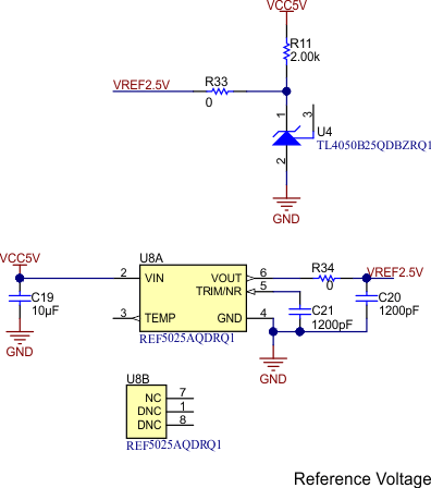
 Figure 3-3 Reference Voltage (VREF = 2.5 V)
VREF2.5V is generated by using the TL4050-Q1 or REF5025-Q1. R33 and R34 are the population variants for choosing the reference voltage. TL4050-Q1 is the typical choice for the reference voltage to support the isolation leakage current measurements.