TIDUDJ6B August 2022 – February 2023 OPA388-Q1
- Description
- Resources
- Features
- Applications
- 5
- 1System Description
- 2System Overview
- 3Hardware, Testing Requirements, and Test Results
- 4Design Files
- 5Software Files
- 6Related Documentation
- 7Trademarks
- 8Revision History
3.2.6 Error Analysis
Isolation error analysis is done based on the requirements from original equipment manufacturers (OEMs), safety goals, and algorithms. This design guide is limited in analyzing the circuit and explaining the error calculations. The error handling part is left to the manufacturers.
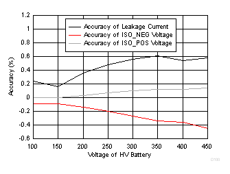
The following measurements were taken with this reference design at various high voltages and under different error conditions:
- Feedback resistor R9, R12 = 5 kΩ
- Series resistance (Pin 3 of relay to input of POS/NEG op amp) = 10 kΩ
- Series resistance (Pin 5 of relay to input of HV POS/HV NEG) = 1.18 MΩ
- Reference voltage (VREF2.5V) = 2.504 V
- C17 and C22 are not populated
| HIGH VOLTAGE | CALCULATED / EXPECTED | MEASURED | ACCURACY | ||||||
|---|---|---|---|---|---|---|---|---|---|
| ISO_POS (V) | ISO_NEG (V) | LEAKAGE CURRENT (mA) | ISO_POS (V) | ISO_NEG (V) | LEAKAGE CURRENT (mA) | ISO_POS (%) | ISO_NEG (%) | LEAKAGE CURRENT (%) | |
| 100.006 | 2.293 | 2.714 | 0.042 | 2.295 | 2.714 | 0.0419 | -0.087 | 0.000 | 0.238 |
| 150.008 | 2.188 | 2.819 | 0.063 | 2.19 | 2.819 | 0.0629 | -0.091 | 0.000 | 0.159 |
| 200.003 | 2.083 | 2.924 | 0.084 | 2.086 | 2.923 | 0.0837 | -0.144 | 0.034 | 0.357 |
| 250.004 | 1.978 | 3.029 | 0.105 | 1.982 | 3.027 | 0.104 | -0.202 | 0.066 | 0.476 |
| 300.004 | 1.873 | 3.134 | 0.126 | 1.878 | 3.131 | 0.125 | -0.267 | 0.096 | 0.556 |
| 350.004 | 1.768 | 3.239 | 0.147 | 1.774 | 3.235 | 0.146 | -0.339 | 0.123 | 0.612 |
| 400.006 | 1.663 | 3.344 | 0.168 | 1.669 | 3.34 | 0.167 | -0.361 | 0.120 | 0.536 |
| 450.007 | 1.558 | 3.449 | 0.189 | 1.565 | 3.444 | 0.1879 | -0.449 | 0.145 | 0.582 |
 Figure 3-37 Accuracy
of Isolation Measurements
Figure 3-37 Accuracy
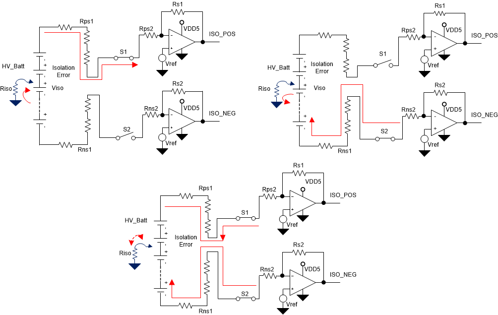
of Isolation MeasurementsAs per GUID-3F19F5ED-1E7C-453B-B476-8C07A0D84BE9.html#T5081059-41 and measurements, the isolation leakage identification is quite straightforward with the isolation error at HV positive or HV negative. Complexity arises when an isolation error is in between the high-voltage positive and negative lines. For the sake of testing this reference design, a potential divider load card is used for isolation error in between battery voltages. The performance of the results shown for these tests may differ to the actual tests for the middle-voltage isolation error, which is one of the less probable errors. The following analysis in #T5081059-45 helps to find the leakage current if there is an isolation error in the middle of the battery.
 Figure 3-38 Isolation Error at Middle of
Battery
Figure 3-38 Isolation Error at Middle of
BatteryIsolation resistance (Riso) and isolation voltage (Viso) can be calculated easily by using the voltages measured before and after closing the switches S1 and S2. Leakage current can be calculated with both isolation error voltage and resistance. When only S1 is closed, the HV_Batt - Vref - Viso voltage is confirmed to be across resistors Riso , Rps1, and Rps2 (neglect bias currents); leakage current can be measured from ISO_POS. When only S2 is closed, the Viso-Vref voltage is confirmed to be across Rns1, Rns2, and Riso, which can be measured from ISO_NEG. By design, resistors Rps1 and Rps2 are the same as Rns1 and Rns2. By using both equations, Riso and Viso can be calculated easily.
In summary, this reference provides a flow chart to monitor the isolation leakage from high voltage to chassis grounds in HEV and EV motors. If the error condition is identified, equations provided in this design guide support the diagnoses of the isolation voltage, isolation resistance, and isolation leakage currents.