TIDUDJ6B August 2022 – February 2023 OPA388-Q1
- Description
- Resources
- Features
- Applications
- 5
- 1System Description
- 2System Overview
- 3Hardware, Testing Requirements, and Test Results
- 4Design Files
- 5Software Files
- 6Related Documentation
- 7Trademarks
- 8Revision History
2.3.2 High-Voltage Measurement
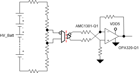
High-voltage measurement is required to calculate the isolation leakage current. In TIDA-01537 , the AMC1301-Q1 device is used to perform these measurements. The AMC1311B has a high input resistance, a 2-V input range, and can also be used for high-voltage measurements.
As #T5081059-27 shows, the Rsh monitoring resistor is placed in series to a high-ohmic potential divider network. Voltage measurements are performed with a floating ground of the AMC1301-Q1. The OPA320-Q1 device is used to amplify the signal range and give a single-ended output to an MCU or logic interface. The AMC1301-Q1 can measure a bidirectional signal of ±250 mV. In HEV or EV motors, battery voltages are only in the positive range, so the usable range of the AMC1301-Q1 is 250 mV. A potential divider network must be chosen in such a way that the voltage drop in shunt resistance must be ≤ 250 mV at the maximum battery voltages.
 Figure 2-11 High-Voltage Measurements
Use #T5081059-57 to calculate the high battery voltage.
where
- VOUT_OPA320 is the output voltage measured by the ADC or relevant device from the output of the OPA320-Q1
- Rsx is the sum of the series resistors from HV_BATT positive to negative including the shunt resistor
- Rsh is the shunt resistor for the AMC1301-Q1
- G_AMC1301 is the gain of the AMC1301-Q1 internal circuit
- G_OPA320 is the gain set by the external resistors for the OPA320-Q1 circuit
#T5081059-57 is a simple equation that does not consider the influences of bias currents or offset voltages, which can lead to deviations in measurements.