JAJSQ90 september 2020 TSB41BA3F-EP
PRODUCTION DATA
- 1
- 1 特長
- 2 アプリケーション
- 3 概要
- 4 Revision History
- 5 Terminal Configuration and Functions
- 6 Specifications
- 7 Operating Life Deration
- 8 Parameter Measurement Information
- 9 Overview
- 10Functional Block Diagram
- 11Principles Of Operation (1394b Interface)
- 12Principles Of Operation (1394a-2000 Interface)
-
13Applications, Implementation, and Layout
- 13.1 Known exceptions to functional specification (errata).
- 13.2
Application Information
- 13.2.1 Interoperability with earlier revisions of TSB41BA3
- 13.2.2 Internal Register Configuration
- 13.2.3 Feature Enhancements to revision F
- 13.2.4 Power-Class Programming
- 13.2.5 Using The TSB41BA3F-EP With A 1394-1995 Or 1394a-2000 Link Layer
- 13.2.6 Power-Up Reset
- 13.2.7 Crystal Selection
- 13.2.8 Bus Reset
- 13.2.9 Designing With Powerpad™ Devices
- 14Device and Documentation Support
- 15Mechanical, Packaging, and Orderable Information
パッケージ・オプション
メカニカル・データ(パッケージ|ピン)
- PFP|80
サーマルパッド・メカニカル・データ
- PFP|80
発注情報
13.2.4 Power-Class Programming
The S2_PC0, S1_PC1, and S0_PC2 terminals can be used in some port speed/mode selections to set the default value of the power-class indicated in the pwr field (bits 21–23) of the transmitted self-ID packet. Descriptions of the various power-classes are given in Table 13-9. The default power-class value is loaded following a hardware reset, but is overridden by any value subsequently loaded into the Pwr_Class field in register 4.
Table 13-9 Power-Class Descriptions
| PC0–PC2 | DESCRIPTION |
|---|---|
| 000 | Node does not need power and does not repeat power. |
| 001 | Node is self-powered and provides a minimum of 15 W to the bus. |
| 010 | Node is self-powered and provides a minimum of 30 W to the bus. |
| 011 | Node is self-powered and provides a minimum of 45 W to the bus. |
| 100 | Node can be powered from the bus and is using up to 3 W; no additional power is needed to enable the link. The node can also provide power to the bus. The amount of bus power that it provides can be found in the configuration ROM. |
| 101 | Reserved for future standardization. |
| 110 | Node is powered from the bus and uses up to 3 W. An additional 3 W is needed to enable the link. |
| 111 | Node is powered from the bus and uses up to 3 W. An additional 7 W is needed to enable the link. |
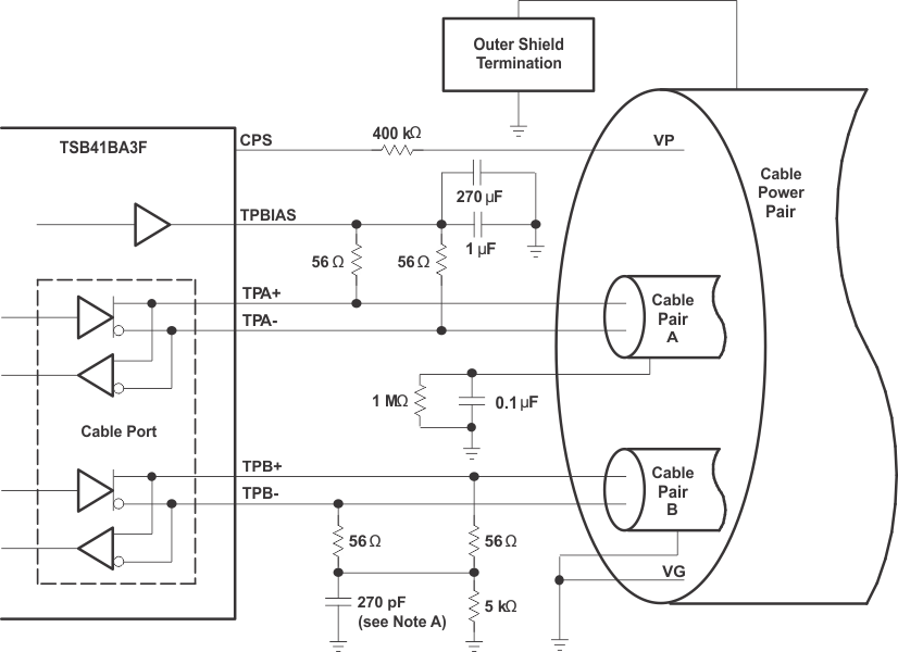
A. The IEEE Std 1394-1995 calls for a 250-pF capacitor, which is a nonstandard component value. A 270-pF capacitor is recommended.
Figure 13-3 Typical TP Cable Connections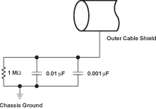 Figure 13-4 Typical DC-Isolated Outer Shield Termination
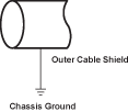 Figure 13-5 Non-DC-Isolated Outer
Shield Termination
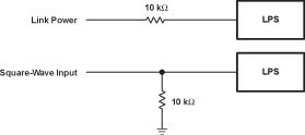 Figure 13-6 Nonisolated Connection Variations For LPS
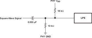 Figure 13-7 Isolated Circuit Connection For LPS