JAJSQ90 september 2020 TSB41BA3F-EP
PRODUCTION DATA
- 1
- 1 特長
- 2 アプリケーション
- 3 概要
- 4 Revision History
- 5 Terminal Configuration and Functions
- 6 Specifications
- 7 Operating Life Deration
- 8 Parameter Measurement Information
- 9 Overview
- 10Functional Block Diagram
- 11Principles Of Operation (1394b Interface)
- 12Principles Of Operation (1394a-2000 Interface)
-
13Applications, Implementation, and Layout
- 13.1 Known exceptions to functional specification (errata).
- 13.2
Application Information
- 13.2.1 Interoperability with earlier revisions of TSB41BA3
- 13.2.2 Internal Register Configuration
- 13.2.3 Feature Enhancements to revision F
- 13.2.4 Power-Class Programming
- 13.2.5 Using The TSB41BA3F-EP With A 1394-1995 Or 1394a-2000 Link Layer
- 13.2.6 Power-Up Reset
- 13.2.7 Crystal Selection
- 13.2.8 Bus Reset
- 13.2.9 Designing With Powerpad™ Devices
- 14Device and Documentation Support
- 15Mechanical, Packaging, and Orderable Information
パッケージ・オプション
メカニカル・データ(パッケージ|ピン)
- PFP|80
サーマルパッド・メカニカル・データ
- PFP|80
発注情報
12.5 Interface Reset and Disable
The LLC controls the state of the PHY-LLC interface using the LPS signal. The interface can be placed into a reset state, a disabled state, or be made to initialize and then return to normal operation. When the interface is not operational (whether reset, disabled, or in the process of initialization), the PHY cancels any outstanding bus request or register read request, and ignores any requests made via the LREQ line. Additionally, any status information generated by the PHY is not queued and does not cause a status transfer on restoration of the interface to normal operation.
The LPS signal can be either a level signal or a pulsed signal, depending on whether the PHY-LLC interface is a direct connection or is made across an isolation barrier. When an isolation barrier exists between the PHY and LLC, the LPS signal must be pulsed. In a direct connection, the LPS signal can be either a pulsed or a level signal. Timing parameters for the LPS signal are given in Table 12-19.
| SYMBOL | DESCRIPTION | MIN | MAX | UNIT | |
|---|---|---|---|---|---|
| tLPSL | LPS low time (when pulsed)(2) | 0.09 | 2.6 | μs | |
| tLPSH | LPS high time (when pulsed)(2) | 0.021 | 2.6 | μs | |
| tLPS_DUTY | LPS duty cycle (when pulsed)(3) | 20% | 60% | ||
| tLPS_RESET | Time for PHY to recognize LPS deasserted and reset the interface | 2.6 | 2.68 | μs | |
| tLPS_DISABLE | Time for PHY to recognize LPS deasserted and disable the interface | 26.03 | 26.11 | μs | |
| tRESTORE | Time to permit optional isolation circuits to restore during an interface reset | 15 | 23(1) | μs | |
| tCLK_ACTIVATE | Time for PCLK to be activated from reassertion of LPS | PHY not in low-power state | 60 | ns | |
| PHY in low-power state | 5.3 | 7.3 | ms | ||
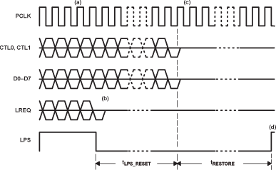
The LLC requests that the interface be reset by deasserting the LPS signal and terminating all bus and request activity. When the PHY observes that LPS has been deasserted for tLPS_RESET, it resets the interface. When the interface is in the reset state, the PHY sets its CTL and D outputs in the logic 0 state and ignores any activity on the LREQ signal. Figure 12-7 shows the timing for interface reset.
 Figure 12-7 Interface Reset
The sequence of events for resetting the PHY-LLC interface is as follows:
- Normal operation. Interface is operating normally, with LPS asserted, PCLK active, status and packet data reception and transmission via the CTL and D lines, and request activity via the LREQ line. In Figure 12-7, the LPS signal is shown as a nonpulsed level signal. However, it is permissible to use a pulsed signal for LPS in a direct connection between the PHY and LLC; a pulsed signal is required when using an isolation barrier.
- LPS deasserted. The LLC deasserts the LPS signal and, within 1 μs, terminates any request or interface bus activity, places its CTL and D outputs into the high-impedance state, and drives its LREQ output low.
- Interface reset. After tLPS_RESET time, the PHY determines that LPS is inactive, terminates any interface bus activity, and drives its CTL and D outputs low. The PHY-LLC interface is now in the reset state.
- Interface restored. After the minimum tRESTORE time, the LLC can again assert LPS active. When LPS is asserted, the interface is initialized as described in the following paragraph.
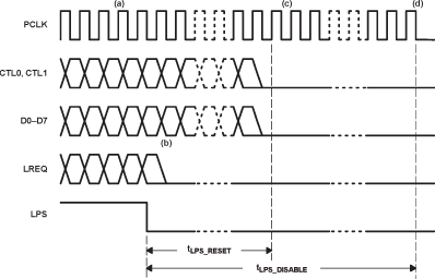
If the LLC continues to keep the LPS signal deasserted, it then requests that the interface be disabled. The PHY disables the interface when it observes that LPS has been deasserted for tLPS_DISABLE. When the interface is disabled, the PHY sets its CTL and D outputs as previously stated for interface reset, but also stops PCLK activity. The interface is also placed into the disabled condition on a hardware reset of the PHY. Figure 12-8 shows the timing for the interface disable.
When the interface is disabled, the PHY enters a low-power state if none of its ports are active.
 Figure 12-8 Interface Disable
The sequence of events for disabling the PHY-LLC is as follows:
- Normal operation. Interface is operating normally, with LPS active, PCLK active, status and packet data reception and transmission via the CTL and D lines, and request activity via the LREQ line.
- LPS deasserted. The LLC deasserts the LPS signal and, within 1 μs, terminates any request or interface bus activity, places its CTL and D outputs into a high-impedance state, and drives its LREQ output low.
- Interface reset. After tLPS_RESET time, the PHY determines that LPS is inactive, terminates any interface bus activity, and drives its CTL and D outputs low. The PHY-LLC interface is now in the reset state.
- Interface disabled. If the LPS signal remains inactive for tLPS_DISABLE time, then the PHY terminates PCLK activity by driving the PCLK output low. The PHY-LLC interface is now in the disabled state.
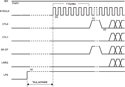
After the interface has been reset, or reset and then disabled, the interface is initialized and restored to normal operation when LPS is reasserted by the LLC. Figure 12-9 shows the timing for interface initialization.
 Figure 12-9 Interface Initialization
The sequence of events for initialization of the PHY-LLC is as follows:
- LPS reasserted. After the interface has been in the reset or disabled state for at least the minimum tRESTORE time, the LLC causes the interface to be initialized and restored to normal operation by reasserting the LPS signal. (In Figure 12-9, the interface is shown in the disabled state with PCLK inactive. However, the interface initialization sequence described here is also executed if the interface is merely reset but not yet disabled.)
- PCLK activated. If the interface is disabled, then the PHY reactivates its PCLK output when it detects that LPS has been reasserted. If the PHY has entered a low-power state, then it takes between 5.3 ms and 7.3 ms for PCLK to be restored; if the PHY is not in a low-power state, then the PCLK is restored within 60 ns. The PCLK output is a 50% duty cycle square wave with a frequency of 49.152 MHz ±100 ppm (period of 20.345 ns). During the first 7 cycles of PCLK, the PHY continues to drive the CTL and D terminals low. The LLC is also required to drive its CTL and D outputs low for one of the first 6 cycles of PCLK but otherwise to place its CTL and D outputs in the high-impedance state. The LLC continues to drive its LREQ output low during this time.
- Receive indicated. On the eighth PCLK cycle following reassertion of LPS, the PHY asserts the receive state on the CTL lines and the data-on indication (all 1s) on the D lines for one or more cycles.
- Initialization complete. The PHY asserts the idle state on the CTL lines and logic 0 on the D lines. This indicates that the PHY-LLC interface initialization is complete and normal operation can commence. The PHY now accepts requests from the LLC via the LREQ line.