SNAA386 November 2023 CDCE6214 , CDCE6214-Q1 , CDCE6214Q1TM , LMK00301 , LMK00304 , LMK00306 , LMK00308 , LMK00334 , LMK00334-Q1 , LMK00338 , LMK03318 , LMK03328 , LMK3H0102 , LMK6C , LMK6H , LMKDB1104 , LMKDB1108 , LMKDB1120 , LMKDB1202 , LMKDB1204
3.3 Spread Spectrum Clocking
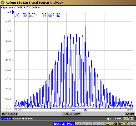
Both Common Clock and Separate Reference architectures allow for Spread Spectrum Clocking. When SSC is used, the frequency of the clock is modulated, which spreads the radiated emissions across multiple frequencies instead of a single peak frequency. This modulation of the frequency increases jitter. Common Clock PCIe systems specify a modulation frequency between 30 kHz and 33 kHz with a spread between 0% and –0.5%, referred to as down-spread SSC. For Separate Reference, the spread range is 0% to –0.3%. Figure 3-3 shows the difference in peak energy for no SSC vs –0.5% down-spread SSC. The single 100 MHz peak at -5 dB is for the no SSC case. With –0.5% down-spread SSC enabled, the peak of the energy is at –14 dB.
If the 100 MHz REFCLK has –0.5% down-spread SSC, then the PCIe devices must be able to tolerate a larger ppm variance from 100 MHz: 100 ppm from the typical frequency stability budget, and 2500 ppm from the spreading of the clock frequency. This specification is typically presented as -100 to +2600 ppm. In SRIS, the maximum down-spread SSC allowed is –0.3%. The total frequency stability in this case is –100 to +1600 ppm.
 Figure 3-3 100 MHz REFCLK With No SSC and
–0.5% Down-Spread SSC
Figure 3-3 100 MHz REFCLK With No SSC and
–0.5% Down-Spread SSCFor Common Clock architectures the jitter is the same for both clocks. As such, the SSC For Separate Reference architectures, the clocks can be Separate Reference No Spread (SRNS), or Separate Reference Independent Spread (SRIS). When SRIS is used, the clock frequencies at the transmitter and receiver at any given time differ. In this case, both PCIe devices to implement buffers to account for the difference in clock frequencies.