SLASF43A December   2023  – September 2026 AFE782H1 , AFE882H1

PRODUCTION DATA  

  1.   1
  2. 1 Features
  3. 2 Applications
  4. 3 Description
  5. 4 Pin Configuration and Functions
  6. 5 Specifications
    1. 5.1  Absolute Maximum Ratings
    2. 5.2  ESD Ratings
    3. 5.3  Recommended Operating Conditions
    4. 5.4  Thermal Information
    5. 5.5  Electrical Characteristics
    6. 5.6  Timing Requirements
    7. 5.7  Timing Diagrams
    8. 5.8  Typical Characteristics: VOUT DAC
    9. 5.9  Typical Characteristics: ADC
    10. 5.10 Typical Characteristics: Reference
    11. 5.11 Typical Characteristics: HART Modem
    12. 5.12 Typical Characteristics: Power Supply
  7. 6 Detailed Description
    1. 6.1 Overview
    2. 6.2 Functional Block Diagram
    3. 6.3 Feature Description
      1. 6.3.1  Digital-to-Analog Converter (DAC) Overview
        1. 6.3.1.1 DAC Resistor String
        2. 6.3.1.2 DAC Buffer Amplifier
        3. 6.3.1.3 DAC Transfer Function
        4. 6.3.1.4 DAC Gain and Offset Calibration
        5. 6.3.1.5 Programmable Slew Rate
        6. 6.3.1.6 DAC Register Structure and CLEAR State
      2. 6.3.2  Analog-to-Digital Converter (ADC) Overview
        1. 6.3.2.1 ADC Operation
        2. 6.3.2.2 ADC Custom Channel Sequencer
        3. 6.3.2.3 ADC Synchronization
        4. 6.3.2.4 ADC Offset Calibration
        5. 6.3.2.5 External Monitoring Inputs
        6. 6.3.2.6 Temperature Sensor
        7. 6.3.2.7 Self-Diagnostic Multiplexer
        8. 6.3.2.8 ADC Bypass
      3. 6.3.3  Programmable Out-of-Range Alarms
        1. 6.3.3.1 Alarm-Based Interrupts
        2. 6.3.3.2 Alarm Action Configuration Register
        3. 6.3.3.3 Alarm Voltage Generator
        4. 6.3.3.4 Temperature Sensor Alarm Function
        5. 6.3.3.5 Internal Reference Alarm Function
        6. 6.3.3.6 ADC Alarm Function
        7. 6.3.3.7 Fault Detection
      4. 6.3.4  IRQ
      5. 6.3.5  HART Interface
        1. 6.3.5.1  FIFO Buffers
          1. 6.3.5.1.1 FIFO Buffer Access
          2. 6.3.5.1.2 FIFO Buffer Flags
        2. 6.3.5.2  HART Modulator
        3. 6.3.5.3  HART Demodulator
        4. 6.3.5.4  HART Modem Modes
          1. 6.3.5.4.1 Half-Duplex Mode
          2. 6.3.5.4.2 Full-Duplex Mode
        5. 6.3.5.5  HART Modulation and Demodulation Arbitration
          1. 6.3.5.5.1 HART Receive Mode
          2. 6.3.5.5.2 HART Transmit Mode
        6. 6.3.5.6  HART Modulator Timing and Preamble Requirements
        7. 6.3.5.7  HART Demodulator Timing and Preamble Requirements
        8. 6.3.5.8  IRQ Configuration for HART Communication
        9. 6.3.5.9  HART Communication Using the SPI
        10. 6.3.5.10 HART Communication Using UART
        11. 6.3.5.11 Memory Built-In Self-Test (MBIST)
      6. 6.3.6  Internal Reference
      7. 6.3.7  Integrated Precision Oscillator
      8. 6.3.8  Precision Oscillator Diagnostics
      9. 6.3.9  One-Time Programmable (OTP) Memory
      10. 6.3.10 GPIO
      11. 6.3.11 Timer
      12. 6.3.12 Unique Chip Identifier (ID)
      13. 6.3.13 Scratch Pad Register
    4. 6.4 Device Functional Modes
      1. 6.4.1 DAC Power-Down Mode
      2. 6.4.2 Register Built-In Self-Test (RBIST)
      3. 6.4.3 Reset
    5. 6.5 Programming
      1. 6.5.1 Communication Setup
        1. 6.5.1.1 SPI Mode
        2. 6.5.1.2 UART Mode
        3. 6.5.1.3 SPI Plus UART Mode
        4. 6.5.1.4 HART Functionality Setup Options
      2. 6.5.2 GPIO Programming
      3. 6.5.3 Serial Peripheral Interface (SPI)
        1. 6.5.3.1 SPI Frame Definition
        2. 6.5.3.2 SPI Read and Write
        3. 6.5.3.3 Frame Error Checking
        4. 6.5.3.4 Synchronization
      4. 6.5.4 UART Interface
        1. 6.5.4.1 UART Break Mode (UBM)
          1. 6.5.4.1.1 Interface With FIFO Buffers and Register Map
      5. 6.5.5 Status Bits
      6. 6.5.6 Watchdog Timer
  8. 7 Register Maps
    1. 7.1 AFEx82H1 Registers
  9. 8 Application and Implementation
    1. 8.1 Application Information
      1. 8.1.1 Multichannel Configuration
    2. 8.2 Typical Application
      1. 8.2.1 4mA to 20mA Current Transmitter
        1. 8.2.1.1 Design Requirements
        2. 8.2.1.2 Detailed Design Procedure
          1. 8.2.1.2.1 Current Loop Control
          2. 8.2.1.2.2 HART Connections
          3. 8.2.1.2.3 Input Protection and Rectification
          4. 8.2.1.2.4 System Current Budget
        3. 8.2.1.3 Application Curves
    3. 8.3 Initialization Setup
    4. 8.4 Power Supply Recommendations
    5. 8.5 Layout
      1. 8.5.1 Layout Guidelines
      2. 8.5.2 Layout Example
  10. 9 Device and Documentation Support
    1. 9.1 Documentation Support
      1. 9.1.1 Related Documentation
    2. 9.2 Receiving Notification of Documentation Updates
    3. 9.3 Support Resources
    4. 9.4 Trademarks
    5. 9.5 Electrostatic Discharge Caution
    6. 9.6 Glossary
  11. 10Revision History
  12. 11Mechanical, Packaging, and Orderable Information

Typical Characteristics: VOUT DAC

at TA = 25°C, PVDD = 2.7V, IOVDD = 1.8V, external or internal VREFIO = 1.25V, RLOAD = 50kΩ to GND, CLOAD = 100pF to GND, and digital inputs at IOVDD or GND (unless otherwise noted)

AFE782H1 AFE882H1 DAC
                        DNL vs Digital Input Code
 
Figure 5-3 DAC DNL vs Digital Input Code
AFE782H1 AFE882H1 DAC
                        INL vs Digital Input Code
 
Figure 5-5 DAC INL vs Digital Input Code
AFE782H1 AFE882H1 DAC
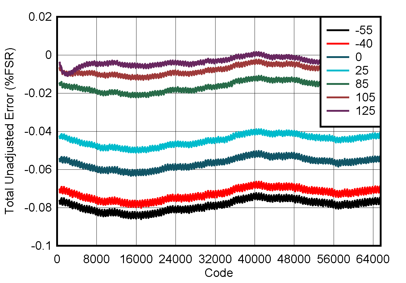
                        TUE vs Digital Input Code
 
Figure 5-7 DAC TUE vs Digital Input Code
AFE782H1 AFE882H1 Zero-code Impedance
 
Figure 5-9 Zero-code Impedance
AFE782H1 AFE882H1 DAC
                        Source and Sink Current Capability
DAC at midcode
Figure 5-11 DAC Source and Sink Current Capability
AFE782H1 AFE882H1 DAC
                        Glitch Impulse Rising Edge
PVDD = 5.5V
Figure 5-13 DAC Glitch Impulse Rising Edge
AFE782H1 AFE882H1 DAC
                        Gain Error vs TemperatureFigure 5-15 DAC Gain Error vs Temperature
AFE782H1 AFE882H1 DAC
                        Full Scale Error vs TemperatureFigure 5-17 DAC Full Scale Error vs Temperature
AFE782H1 AFE882H1 DAC
                        Output Noise, 0.1Hz to 10Hz
DAC at midcode PVDD = 5.5V
Figure 5-19 DAC Output Noise, 0.1Hz to 10Hz
AFE782H1 AFE882H1 DAC
                        Rising Settling Time
 
Figure 5-21 DAC Rising Settling Time
AFE782H1 AFE882H1 DAC
                        Settling Time With Linear Slew Rate Control
 
Figure 5-23 DAC Settling Time With Linear Slew Rate Control
AFE782H1 AFE882H1 DAC
                            RESET Response
 
Figure 5-25 DAC RESET Response
AFE782H1 AFE882H1 DAC
                        AC PSRR vs Frequency
Internal reference
Figure 5-27 DAC AC PSRR vs Frequency
AFE782H1 AFE882H1 MIN
                        and MAX DAC DNL Range vs Temperature
 
Figure 5-4 MIN and MAX DAC DNL Range vs Temperature
AFE782H1 AFE882H1 MIN
                        and MAX DAC INL Range vs Temperature
 
Figure 5-6 MIN and MAX DAC INL Range vs Temperature
AFE782H1 AFE882H1 MIN
                        and MAX DAC TUE vs Temperature
 
Figure 5-8 MIN and MAX DAC TUE vs Temperature
AFE782H1 AFE882H1 DAC
                        Footroom Over Temperature and Load
 
Figure 5-10 DAC Footroom Over Temperature and Load
AFE782H1 AFE882H1 DAC
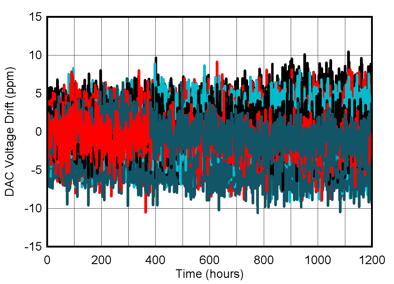
                        Output Voltage Long-Term Stability
Ideal reference
Figure 5-12 DAC Output Voltage Long-Term Stability
AFE782H1 AFE882H1 DAC
                        Glitch Impulse Falling Edge
PVDD = 5.5V
Figure 5-14 DAC Glitch Impulse Falling Edge
AFE782H1 AFE882H1 DAC
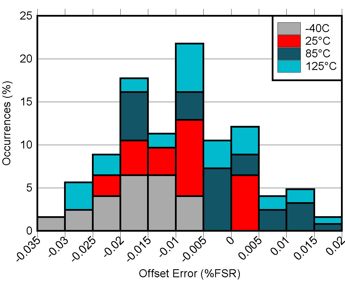
                        Offset Error vs TemperatureFigure 5-16 DAC Offset Error vs Temperature
AFE782H1 AFE882H1 DAC
                        Zero Scale Error vs TemperatureFigure 5-18 DAC Zero Scale Error vs Temperature
AFE782H1 AFE882H1 DAC
                        Output Noise Density vs Frequency
DAC at midcode PVDD = 5.5V
Figure 5-20 DAC Output Noise Density vs Frequency
AFE782H1 AFE882H1 DAC
                        Falling Settling Time
 
Figure 5-22 DAC Falling Settling Time
AFE782H1 AFE882H1 DAC
                        Settling Time With Sinusoidal Slew Rate Control
 
Figure 5-24 DAC Settling Time With Sinusoidal Slew Rate Control
AFE782H1 AFE882H1 DAC
                        Supply Power On, PVDD = 2.7V
 
Figure 5-26 DAC Supply Power On, PVDD = 2.7V