SLLA383A February 2018 – August 2022 SN65HVDA100-Q1 , SN65HVDA195-Q1 , TLIN1022-Q1 , TLIN1029-Q1 , TLIN2022-Q1 , TLIN2029-Q1 , TMS320F28P550SG , TMS320F28P550SJ , TMS320F28P559SG-Q1 , TMS320F28P559SJ-Q1
3 Physical Layer Requirements
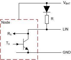
The LIN physical layer is based on the ISO 9141 standard, with some modifications for automotive applications; specifically EMC, ESD, Transient pulse response, and so forth. It is a bus communication interface that is bidirectional, biased to the battery voltage of the vehicle through a resistor and diode (commander node only), and is connected to the transceiver of every node in the LIN cluster.
The transceiver is what facilitates the communication between the bus and the network. The LIN transceiver converts the bit logic from the microcontroller into higher voltage levels, as a transmission along the bus and vice versa. The TXD (transmit) and RXD (receive) of the LIN transceiver, facilitate the communication to and from the bus through voltage translation that happens as the signals pass through the transceiver. The TXD is connected to the microcontroller, where the message is sent and then broadcasted on the LIN bus. The RXD monitors the bus and converts the messages on the LIN bus to voltage levels the microcontroller can interpret, and thus respond to the communication happening on the bus. Typical voltage levels for the TXD and RXD are typical of most microcontroller levels: 3.3 V and 5 V. The LIN bus and LIN transceivers usually operate at voltages ranging from 9 V to 18 V, but some can go up to 30 V (depending on the application). A typical vehicle is a 12-V battery system, but some larger vehicles go up to 24 V.
 Figure 3-1 Simplified LIN Driver Schematic