SLLA383A February 2018 – August 2022 SN65HVDA100-Q1 , SN65HVDA195-Q1 , TLIN1022-Q1 , TLIN1029-Q1 , TLIN2022-Q1 , TLIN2029-Q1 , TMS320F28P550SG , TMS320F28P550SJ , TMS320F28P559SG-Q1 , TMS320F28P559SJ-Q1
3.3 Threshold Values
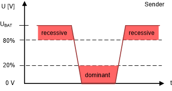
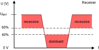
The sender and receiver have different levels that meet these recessive and dominant voltage level requirements. For dominant pulses (low), the sender must drive the voltage level down to 20% of the battery voltage level, while the receiver will interpret a dominant bit when the voltage level reaches 40% on their end. For recessive pulses (high), the sender must drive the voltage to 80% of the battery voltage, while the receiver interprets a recessive bit when the voltage level reaches 60% on the bus. The difference in levels between the receiver and sender is due to differences in the external supply voltage and the actual LIN bus voltage. Drops in voltage that may happen in the cabling, ground shifts, or just changes caused by filtering components along the bus are the main causes for the deviation of the external supply versus the bus level.
 Figure 3-2 Bus Signal Thresholds for Senders
 Figure 3-3 Bus Signal Thresholds for Receivers