SLLA383A February 2018 – August 2022 SN65HVDA100-Q1 , SN65HVDA195-Q1 , TLIN1022-Q1 , TLIN1029-Q1 , TLIN2022-Q1 , TLIN2029-Q1 , TMS320F28P550SG , TMS320F28P550SJ , TMS320F28P559SG-Q1 , TMS320F28P559SJ-Q1
3.5 Synchronization and Bit Sampling
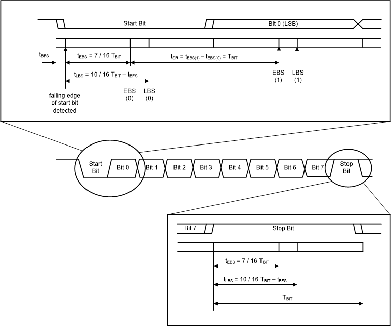
Barring a special use case, all bit times use the bit timing of the commander node as the reference. The synch byte consists of ‘0x55’ (8 bits of alternating 1’s and 0’s, starting with 0) which is essentially a clock signal at a given frequency. The falling edges of the pattern are used for synchronizations that are combined with the start and stop bit (10 bits total), which allows 4 total falling edges for synchronization of the responder nodes. This also allows for accurate bit width (TBIT) measurement. However, because of different methods of synchronization on the market being used in terms of bit sampling (not necessarily on the falling edge of the start bit), the LIN 2.2 specification removed the specification of start-bit sampling. This allows all methods for start-bit sampling that meet the timing requirements of the byte field synchronization (tBFS, which is defined as 1/16 of TBIT typical, 2/16 TBIT maximum).
 Figure 3-4 Bit Sampling Illustrated
After synchronization of the responder nodes occurs, each bit must be sampled accurately to ensure proper interpretation of the message by the LIN cluster. Each bit shall be sampled between the earliest bit sample (tEBS) and the latest bit sample (tLBS); tLBS is dependent on tBFS via Equation 1:
TEBS is defined as minimum 7/16 TBIT. The rest of the bits after the first bit are then sampled with a sample rate (tSR). These are based on the earliest bit sample of the former bit (n – 1) and the earliest bit sample of the current bit (n), and given by the following equation: