SLVAE30E February 2021 – March 2021 TPS1H000-Q1 , TPS1H100-Q1 , TPS1H200A-Q1 , TPS1HA08-Q1 , TPS25200-Q1 , TPS27S100 , TPS2H000-Q1 , TPS2H160-Q1 , TPS2HB16-Q1 , TPS2HB35-Q1 , TPS2HB50-Q1 , TPS4H000-Q1 , TPS4H160-Q1
- Trademarks
- 1Introduction
- 2Driving Resistive Loads
- 3Driving Capacitive Loads
- 4Driving Inductive Loads
- 5Driving LED Loads
- 6Appendix
- 7References
- 8Revision History
2.4.1 Power Dissipation Calculation
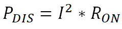
The choice of the correct smart high side switch is weighted heavily by whether or not the device can provide the current required for the application without reaching thermal shutdown. For resistive load applications the first thing that needs to be done is measuring the resistance of the load. Then using Equation 1 the current can be calculated. Note that the voltage provided needs to be the maximum operating voltage desired for a specific use case. For car batteries this would be 18V and anything higher would be considered a fault case. Most resistive loads will not be ran at full current due to the PWMing of the input, but it is important to make sure that the switch will still be able to operate in this condition. This can happen during a reverse battery fault when the current cannot be regulated by the PWM. Using this current and the RON of the switch (maximum at high temperature), the power dissipated in the switch can be calculated by Equation 4.
To calculate the junction temperature of a device a designer can find the junction-to-ambient thermal resistance, RθJA, in the Thermal Information section of the datasheet. Notice that the RθJA in the datasheet is specified for a specific board layout defined by the JEDEC standard. The thermal performance will change for different board layouts, but this gives a good first approximation. For a full calculation please run thermal simulations of the device to see what the temperature will be. Calculating the junction temperature, TJ, on a first order basis is taking the ambient temperature, TA, plus the power dissipated times the RθJA as shown,

All of TI's Smart High Side Switches have a thermal shutdown capability. This means that when the junction temperature of the device reaches a certain temperature the device will shut off to protect itself. When a system is in normal operation it should be designed such that the switch should never reach that temperature. Using the equation above and relating the maximum junction temperature calculated with the thermal shutdown threshold in the datasheet, T(SD) or TABS, will let the designer know if the device will shut off because of the current required driving this load. Note that this is for the use case where there is no PWMing of the load. When the load is PWMed the current in the system is lower than the DC current calculated in the section. This means that designers can actually choose their smart high side switch based on the PWM'd current and due to TI's adjustable current limiting, can set the current limit below DC operation.