SLVAEP5A April 2020 – June 2021 LM3668 , TPS63000 , TPS63000-Q1 , TPS63001 , TPS63002 , TPS63010 , TPS63011 , TPS63020 , TPS63020-Q1 , TPS63021 , TPS63024 , TPS630241 , TPS630242 , TPS630250 , TPS630251 , TPS630252 , TPS63027 , TPS63030 , TPS63031 , TPS63036 , TPS63050 , TPS63051 , TPS63060 , TPS63061 , TPS63070 , TPS63802 , TPS63805 , TPS63806 , TPS63810 , TPS63811 , TPS63900 , TPS63901
5 Additional Capacitors to a Chassis Ground
From an antenna theory point of view, a cable is nothing more than a radiator. The chassis or the enclosure where the converter is located can serve as the reference plane for this radiator. The potential difference between the cable and the chassis is the voltage driving this antenna. Due to this phenomenon, external cables, like those used to connect to a power supply, can be a major source of radiation. To minimize these radiations, it is important to control and reduce the previously mentioned potential difference. A good way to do this is to provide a high frequency, low-impedance connection between the chassis and the PCB pins that are connected to potential radiators.
To adapt this principle to TPS63070 converter PCB, the bottom plane has been replaced by a neutral chassis ground. High-frequency capacitors have been used to connect this new ground layer to the input, output, and ground planes. This way, a low impedance path is provided for high-frequency signals.
Please be aware that these capacitors should be placed as close as possible to the cable terminations on the PCB. By doing this, we can ensure a minimal voltage difference between chassis ground and the connected plane.
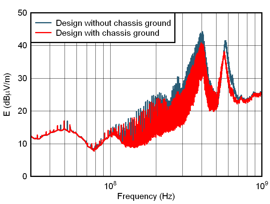
Figure 5-1 shows the benefits of this solution to the overall design. The radiated field is reduced at all frequencies with no significant trade-offs. By implementing this solution, an additional 5 dB decrease in radiated emissions can be achieved.
 Figure 5-1 Changes in Radiated Emissions
when Connecting the Chassis Ground