SLVAF66 June 2021 DRV3255-Q1 , DRV8300 , DRV8301 , DRV8302 , DRV8303 , DRV8304 , DRV8305 , DRV8305-Q1 , DRV8306 , DRV8307 , DRV8308 , DRV8320 , DRV8320R , DRV8323 , DRV8323R , DRV8340-Q1 , DRV8343-Q1 , DRV8350 , DRV8350F , DRV8350R , DRV8353 , DRV8353F , DRV8353R
- 1 Introduction to High-Power Motor Applications
- 2 Examining a High-Power Motor Drive System at a High Level
- 3 High-Power Design Through MOSFETs and MOSFET Gate Current (IDRIVE)
- 4 High-Power Design Through External Components
- 5 High-Power Design Through a Parallel MOSFET Power Stage
- 6 High-Power Design Through Protection
- 7 High-Power Design Through Motor Control Methods
- 8 High-Power Design Through Layout
- 9 Conclusion
- 10Acknowledgments
4.1.1 Note on Capacitor Voltage Ratings
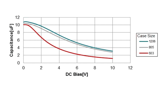
Ceramic capacitors have poor DC voltage derating. This is a known disadvantage of using a ceramic capacitor instead of a different material, like an aluminum oxide electrolytic. A ceramic capacitor experiences one half of the rated capacitance when exposed to the rated voltage.
 Figure 4-2 Capacitance vs Voltage Exposed
to Capacitor by Package Size
Figure 4-2 Capacitance vs Voltage Exposed
to Capacitor by Package SizeFigure 4-2 shows an actual production capacitor example. Observe, the 10-μF capacitor rated for 10 V results in an equivalent capacitance of only 1–3 μF when biased at 10 V. These graphs are found in any capacitor data sheet and other engineers have already explored and exposed these facts.
In the context of high power, a 48-V system needs ceramic capacitors rated for a minimum of 100 V, or 2 multiplied by 48 V, which equals 96 V with the closest industry rating at 100 V. As a result, 48-V rated capacitors in the power stage are not helpful and must be sized accordingly.
Note, this guideline is sometimes relaxed to 1.5 multiplied by the supply voltage, as in the case of 60-V applications where multiplying by 2 gives 120 V which sits between the 100 V and 150 V industry standard. Therefore, the 1.5 times 60 V calculates to 90 V or 100 V, just like the 48-V case. As Figure 4-2 shows, this guideline may fail and it is recommended to consult the data sheet of the capacitor for more information.
In summary:
- Effective capacitance decreases when more voltage is exposed to a capacitor
- Choose capacitors with voltage ratings at 2 or
1.5 times the typical voltage that the capacitors are exposed to:
- This is approximately a 100-V rating for 48-V systems
- Ceramic capacitors have much worse voltage
derating compared to aluminum capacitors so the general guidelines do not apply
to aluminum electrolytic capacitors
- It is recommended to check the data sheet of the capacitor for the exact derating provided by the manufacturer