SLVUDY2 November   2026


  1.   1
  2.   Description
  3.   Get Started
  4.   Features
  5.   Applications
  6.   6
  7. 1Evaluation Module Overview
    1. 1.1 Introduction
    2. 1.2 Kit Contents
    3. 1.3 Specification
    4. 1.4 Device Information
  8. 2Hardware
    1. 2.1 Hardware Overview
    2. 2.2 Jumper Information
      1. 2.2.1 PA10 and PA11 Connection Terminals
      2. 2.2.2 Bottom Sigma Delta Header Block
    3. 2.3 Power Requirements
    4. 2.4 XDS110 Debug Probe
      1. 2.4.1 Isolation Jumper Block
    5. 2.5 Measure Current Draw of the MSPM0G3708
    6. 2.6 Clocking
    7. 2.7 BoosterPack Plug-in Module Pinout
    8. 2.8 Sigma Delta ADC Inputs
  9. 3Software
    1. 3.1 Software Development Options
    2. 3.2 TI Energy Metrology Studio
    3. 3.3 Software Development: CCS
  10. 4Hardware Design Files
    1. 4.1 Schematics
    2. 4.2 PCB Layouts
    3. 4.3 Bill of Materials (BOM)
  11. 5Additional Information
    1. 5.1 Compliance and Certifications
    2. 5.2 Trademarks

Power Requirements

The LP-MSPM0G3708 only needs the USB plugged in and the debugger jumper block populated to power the device. With the onboard LDO, the 5V USB supply is converted to 3.3V with a supply of 500mA. The LaunchPad can also be powered by the 3.3V or 5V headers using an external supply. Do not exceed 3.3V on the 3.3V rail or 5V on the 5V rail.
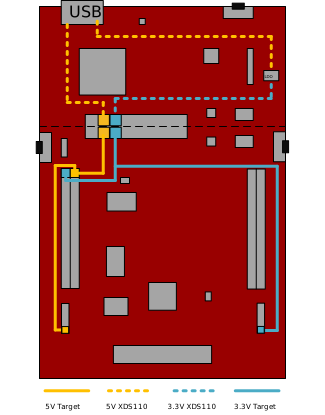
LP-MSPM0G3708 LP-MSPM0G3708 Power
          Connections Figure 2-2 LP-MSPM0G3708 Power Connections