SLYY203B September 2021 – April 2023 BQ25125 , LM5123-Q1 , LMR43610 , LMR43610-Q1 , LMR43620 , LMR43620-Q1 , TPS22916 , TPS3840 , TPS62840 , TPS63900 , TPS7A02
- 1
- Overview
- At a glance
- Contributors to IQ
- Why low IQ creates new challenges
- How to break low IQ barriers
-
Electrical Characteristics
- 18
- Avoiding potential system pitfalls in a low-IQ designs
- Achieving low IQ, but not losing flexibility
- Reducing external component count to lower IQ in automotive applications automotive applications
- Smart on or enable features supporting low-IQ at the Smart on or enable features supporting low-IQ at the system level
- Conclusion
- Key product categories for low IQ
Avoiding potential system pitfalls in a low-IQ designs
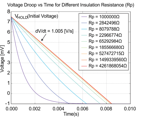
The leakage of external capacitors is a concern. Both the input and output capacitors of any regulator adds to IQ. An excellent way to evaluate the leakage of external capacitors is described in Figure 19, where the voltage droop is measured on the capacitor vs. time for different capacitor insulation resistance (Rp) specifications. It’s a good idea to measure the leakage on the capacitors independent of what the data sheet says. Charging a capacitor to a known voltage and monitoring the droop over time is an excellent way to quantify and compare different capacitor options. The capacitor with the largest insulation resistance will show the least droop over time.
 Figure 19 Voltage droop vs. time for
different insulation resistances.
Figure 19 Voltage droop vs. time for
different insulation resistances.Besides capacitor leakages, the input impedance of a voltmeter can play a significant role in low-IQ measurement setups and lead to incorrect results. Placed at the input or output of the power regulator, a typical 10-MΩ impedance voltmeter contributes 500 nA in the case of a 5-V supply or output voltage. This external leakage is 20 times more than the internal self-consuming IQ of the 25-nA IQ for the TPS7A02 LDO.
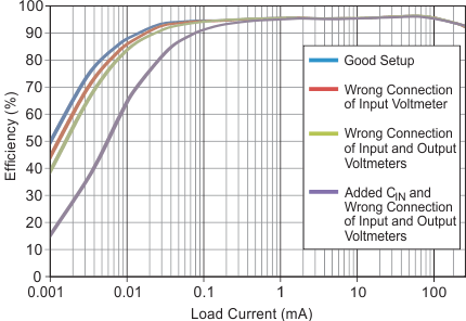
It is possible to avoid measurement errors with the correct measurement methods and the correct placement of volt and current meters. Figure 20 shows the impact on efficiency with different test setups, which become quite significant already lower than a 0.1 mA load. For tips on the best options to avoid setup issues for ultra-low IQ measurements, see the Analog Design Journal article, Accurately measuring efficiency of ultra-low-IQ devices.
 Figure 20 Different efficiency
measurement results dependent on the setup.