SLYY203B September 2021 – April 2023 BQ25125 , LM5123-Q1 , LMR43610 , LMR43610-Q1 , LMR43620 , LMR43620-Q1 , TPS22916 , TPS3840 , TPS62840 , TPS63900 , TPS7A02
- 1
- Overview
- At a glance
- Contributors to IQ
- Why low IQ creates new challenges
- How to break low IQ barriers
-
Electrical Characteristics
- 18
- Avoiding potential system pitfalls in a low-IQ designs
- Achieving low IQ, but not losing flexibility
- Reducing external component count to lower IQ in automotive applications automotive applications
- Smart on or enable features supporting low-IQ at the Smart on or enable features supporting low-IQ at the system level
- Conclusion
- Key product categories for low IQ
Addressing transient response issues
The key to improving the transient response is to start with the best topology. For example, the TPS61094 supports low IQ and fast transient response. The TPS61094 is a bi-directional buck/boost converter that has a low IQ of 60nA in supercapacitor-charging (buck) and supercapacitor-discharging (boost) modes. The TPS61094 monitors dv/dt slopes at the output and adjusts its regulation behavior to optimize the transient performance at any given moment. This allows to quickly detect an output voltage drop while maintaining low IQ at the same time. As a result, the output voltage will remain nearly constant when the TPS61094 starts supporting backup power or peak load support from a supercapacitor.
You must reduce the number of current-consuming blocks as much as possible, so the simpler the topology, the better. For example, the TPS63900 four-switch buck-boost converter, which has an IQ of 75nA, uses one single mode to regulate the output voltage above, below or equal to the input level. Besides the core architecture, using sample-and-hold techniques when entering light load minimizes the ISHDN of all internal support functions.
You can conserve even more current with a zero-current feedback divider, digital assisted control and dynamic biasing. Dynamic biasing is a well-known technique, but becomes challenging when operating with just a few nanoamperes. To avoid the gain falloff at low bias currents, optimally shaping both the transconductance and output resistance as a function of the bias current achieves an IQ-efficient constant gain amplifier.
Another technique uses fast startup circuits. By reducing the startup time of the sample-and-hold reference systems, the on time of the band-gap core and scaling amplifier circuits are reduced significantly. This improves the on-to-off time ratio, thus bringing the average current down in the nanoampere range while maintaining noise and accuracy levels.
To improve the line transient response, feed-forward techniques are applied to the voltage regulation loop in an energy-efficient way. Using transient detection circuits to adjust bias currents or enable circuitry further reduces both voltage dips at the output and settling times.
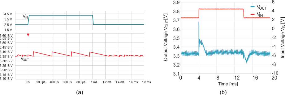
Figure 11 illustrates the application of these techniques in the TPS63900. The line transient is barely visible on the output voltage and far below the switching ripple, whereas other devices show 100-mV changes.
 Figure 11 Line transient response with
VIN = 2.5V to 4.2V, VOUT = 3.3V, IOUT =
1mA: TPS63900 (a); competing device (b).