SLYY203B September 2021 – April 2023 BQ25125 , LM5123-Q1 , LMR43610 , LMR43610-Q1 , LMR43620 , LMR43620-Q1 , TPS22916 , TPS3840 , TPS62840 , TPS63900 , TPS7A02
- 1
- Overview
- At a glance
- Contributors to IQ
- Why low IQ creates new challenges
- How to break low IQ barriers
-
Electrical Characteristics
- 18
- Avoiding potential system pitfalls in a low-IQ designs
- Achieving low IQ, but not losing flexibility
- Reducing external component count to lower IQ in automotive applications automotive applications
- Smart on or enable features supporting low-IQ at the Smart on or enable features supporting low-IQ at the system level
- Conclusion
- Key product categories for low IQ
Contributors to IQ
IQ is the amount of current used when the integrated circuit (IC) is enabled but not switching nor supporting an external load current. Shutdown current (ISHDN) is the current drawn from the supply when the device is disabled.
The IQ of always-on functions such as power regulators contribute to the overall IQ of systems with long standby times. Inside the power regulators themselves, the voltage reference, error amplifier, output voltage divider and protection circuits all have their own operating currents.
To determine the total IQ drawn from a battery or power supply, you must consider the always-on functions and leakage sources from capacitors, resistors and inductors.
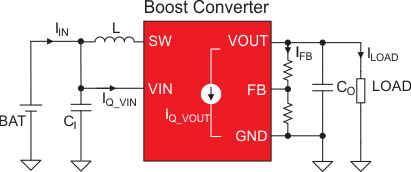
For the IQ of switching converters, some distinctions must be made. Switching converters usually include a power-save mode that enables a longer non-switching period, thereby reducing average IQ. But because the IQ does not include switching currents or the efficiency component of currents drawn from the voltage output (VOUT), like in the example of a boost converter in Figure 4, Equation 1 can be used to calculate a superset of the input-referred no-load operating currents for almost any regulator as:
Currents and voltages are explained in Figure 4, where:
- IQ (VIN ) is the VIN-referred IQ (the IC data-sheet value).
- ILeakage(VIN) is the leakage drawn on the VIN pin from capacitors, inductors, diodes or switches.
- VOUT is the output voltage.
- VIN is the battery voltage (the input voltage to the LDO, boost or buck-boost converter).
- ƞ1 is the DC/DC efficiency when the converter is switching.
- IQ (VOUT ) is the IQ drawn on the switching converter’s VOUT pin. For an LDO, IQ (VOUT ) = 0.
- IFB is the current of the feedback resistor divider, if applicable.
- ILoad is the load current potentially present on VOUT in standby mode.
 Figure 4 Currents in a boost converter
system.
Figure 4 Currents in a boost converter
system.If you know the battery capacity and have calculated the input-referred standby current, Equation 2 estimates the battery life for a heavily duty-cycled low-power system in standby mode >99.9% of the time as:
For example, the battery of a duty-cycled system with 1.2 µA of standby current can last as 8.7 years on a 100-mAh coin-cell battery.