SLYY203B September 2021 – April 2023 BQ25125 , LM5123-Q1 , LMR43610 , LMR43610-Q1 , LMR43620 , LMR43620-Q1 , TPS22916 , TPS3840 , TPS62840 , TPS63900 , TPS7A02
- 1
- Overview
- At a glance
- Contributors to IQ
- Why low IQ creates new challenges
- How to break low IQ barriers
-
Electrical Characteristics
- 18
- Avoiding potential system pitfalls in a low-IQ designs
- Achieving low IQ, but not losing flexibility
- Reducing external component count to lower IQ in automotive applications automotive applications
- Smart on or enable features supporting low-IQ at the Smart on or enable features supporting low-IQ at the system level
- Conclusion
- Key product categories for low IQ
Addressing other noise issues
Beyond switching noise, continuous self-noise, with thermal and flicker noise components in the range of 0.1Hz to 100kHz, are of concern at lower IQ biasing. Because the reference is usually the largest noise contributor, choosing integrated versions of sample-and-hold techniques to create both voltage and current references offer a compelling trade-off between area, noise, IQ and robust performance (no drift) over the life of the device. The drawback of such sample-and-hold circuits are the small ripple errors created.
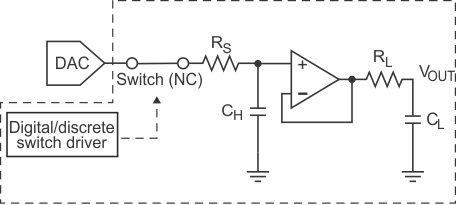
Figure 13 illustrates a design using TI’s precision digital-to-analog converter (DAC) and operational amplifier families that attempts to optimize sample-and-hold operation so that any glitch created is well within the noise floor of the regulator in question. Some of these techniques are employed to remove the glitch and unwanted tones in TPS7A02 LDO design.
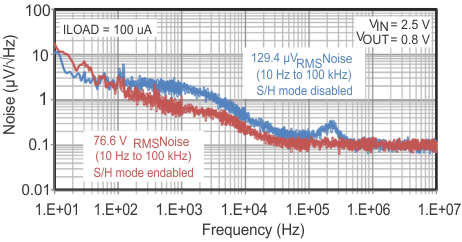
As shown in Figure 14, the TPS7A02 device’s sample-and-hold noise-shaping reduces integrated noise >40% in the 10 to 100Hz frequency band.
 Figure 14 Noise spectrum with and
without a sample-and-hold reference on the TPS7A02. (Source: TI internal silicon
measurements on the TPS7A02).