SWRA705 August 2021 AWR1243 , AWR1443 , AWR1642 , AWR1843 , AWR1843AOP , AWR2243 , AWR2944 , AWR6443 , AWR6843 , AWR6843AOP , AWRL1432 , AWRL6432 , IWR1443 , IWR1642 , IWR1843 , IWR2243 , IWR2944 , IWR6243 , IWR6443 , IWR6843 , IWR6843AOP , IWRL6432 , IWRL6432AOP
2.2 Impedance Mismatch at Radome Boundaries
Electromagnetic wave reflections occur at the boundaries of the plane of mismatch. This plane of mismatch could be considered as boundary of two medium with different dielectric properties, that is, mediums with different permittivity as shown in Figure 2-1.
 Figure 2-1 Boundary of Mismatch Between
Dielectric Mediums
Figure 2-1 Boundary of Mismatch Between
Dielectric MediumsThese reflections due to impedance mismatch can be better understood by looking into electromagnetic wave interaction at the impedance mismatch planes. The interaction of the electromagnetic wave at these planes leads to the reflection and transmission of waves at the boundary of medium, which is quantized in terms of reflection coefficient Γ and transmission coefficient . The reflection coefficient is the ratio of reflected Er and incident Ei electric field strength and transmission coefficient is the ratio of transmitted Et and incident Ei electric field strength as shown in Equation 1 and Equation 2.


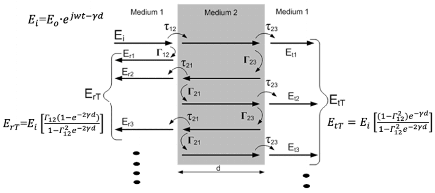
Essentially, there will be multiple reflections occurring within the radome material and resulting in the accumulation shown in Figure 2-2. This results in a reflected wave (ErT) and transmitted wave (EtT) created from the incident wave (Eri).
 Figure 2-2 Multiple Reflections at
Boundaries of Dielectric Mediums
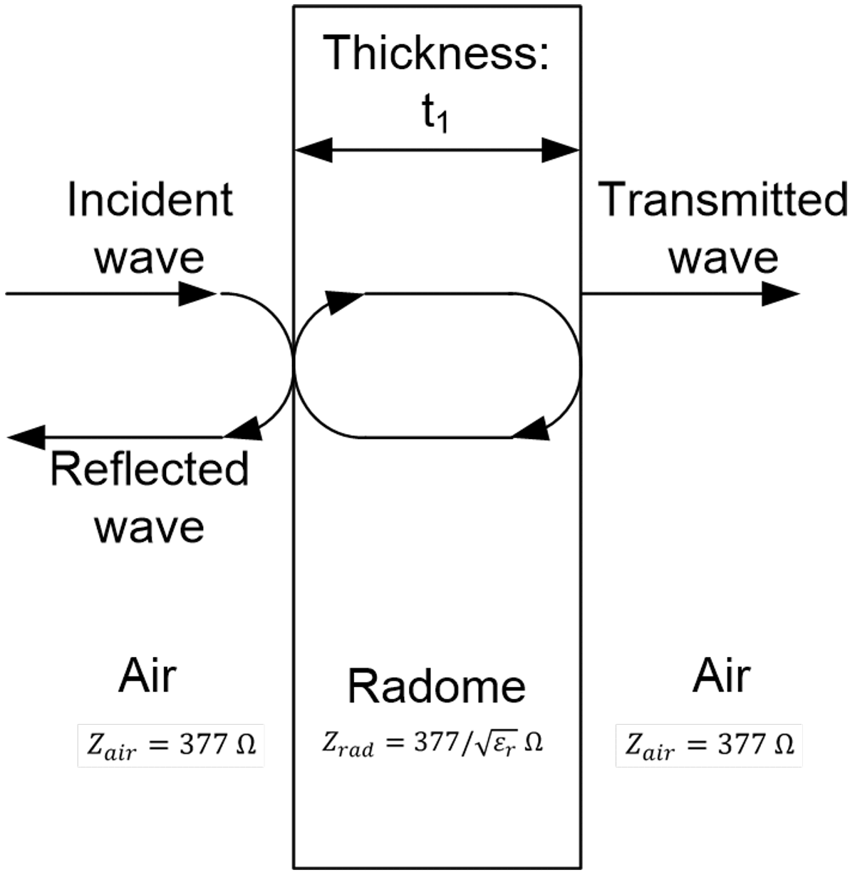
 Reflections within the radome can be simplified as shown in Figure 2-3. Free space or air wave impedance is about 377Ω such that the wave impedance inside the radome is given by 377/√εr Ω. Electromagnetic waves will be reflected back from such that both the air-radome interface and radome-air interface.
 Figure 2-3 Reflections at Radome
Boundaries (assumption is that radome has a solid single wall