SBOS891C October   2018  – September 2023 TMP144

PRODUCTION DATA  

  1.   1
  2. Features
  3. Applications
  4. Description
  5. Revision History
  6. Pin Configuration and Functions
  7. Specifications
    1. 6.1 Absolute Maximum Ratings
    2. 6.2 ESD Ratings
    3. 6.3 Recommended Operating Conditions
    4. 6.4 Thermal Information
    5. 6.5 Electrical Characteristics
    6. 6.6 UART Interface Timing
    7. 6.7 Timing Diagrams
    8. 6.8 Typical Characteristics
  8. Detailed Description
    1. 7.1 Overview
    2. 7.2 Functional Block Diagram
    3. 7.3 Feature Description
      1. 7.3.1 Power Up
      2. 7.3.2 Digital Temperature Output
      3. 7.3.3 Timeout Function
    4. 7.4 Device Functional Modes
      1. 7.4.1 Continuous Conversion Mode
      2. 7.4.2 Shutdown Mode
      3. 7.4.3 One-Shot Mode
      4. 7.4.4 Extended Temperature Mode
      5. 7.4.5 Temperature Alert Function
      6. 7.4.6 Interrupt Functionality
    5. 7.5 SMAART Wire / UART Interface
      1. 7.5.1 Communication Protocol
      2. 7.5.2 Global Software Reset
      3. 7.5.3 Global Initialization and Address Assignment Sequence
      4. 7.5.4 Global Clear Interrupt
      5. 7.5.5 Global Read and Write
      6. 7.5.6 Individual Read and Write
    6. 7.6 Register Maps
      1. 7.6.1 Temperature Result Register (P[1:0] = 00) [reset = 0000h]
      2. 7.6.2 Configuration Register (P[1:0] = 01) [reset = 0200h]
      3. 7.6.3 Temperature Low Limit Register (P[1:0] = 10) [reset = F600h]
      4. 7.6.4 Temperature High Limit Register (P[1:0] = 11) [reset = 3C00h]
  9. Application and Implementation
    1. 8.1 Application Information
    2. 8.2 Typical Application
      1. 8.2.1 Design Requirements
      2. 8.2.2 Detailed Design Procedure
        1. 8.2.2.1 Trace Length
        2. 8.2.2.2 Voltage Drop Effect
        3. 8.2.2.3 Power Supply Noise Filtering
      3. 8.2.3 Application Curves
    3. 8.3 Power Supply Recommendations
    4. 8.4 Layout
      1. 8.4.1 Layout Guidelines
      2. 8.4.2 Layout Example
  10. Device and Documentation Support
    1. 9.1 Device Support
      1. 9.1.1 Device Nomenclature
    2. 9.2 Receiving Notification of Documentation Updates
    3. 9.3 Support Resources
    4. 9.4 Trademarks
    5. 9.5 Electrostatic Discharge Caution
    6. 9.6 Glossary
  11. 10Mechanical, Packaging, and Orderable Information

Package Options

Refer to the PDF data sheet for device specific package drawings

Mechanical Data (Package|Pins)
  • YBK|4
  • YFF|4
  • YMT|4
Thermal pad, mechanical data (Package|Pins)
Orderable Information

Description

The TMP144 digital output temperature sensor can read temperatures to a resolution of 0.0625°C.

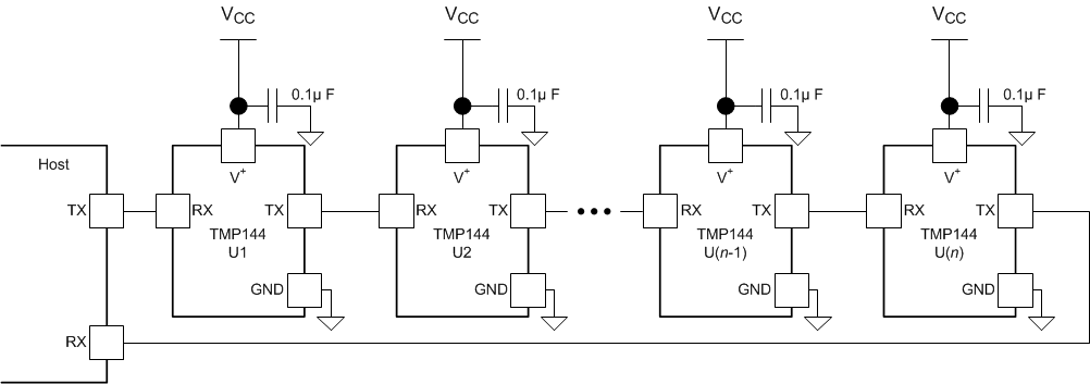
The device has a SMAART Wire™ / UART interface that supports daisy-chain configurations. The interface also supports Multiple Device Access (MDA) commands that let the host communicate with multiple devices on the bus simultaneously. MDA commands are used as an alternative to sending individual commands to each device on the bus. Up to 16 TMP144 devices can be attached together serially and can be read by the host computer.

The TMP144 device is designed for space-constrained, power-sensitive applications with multiple temperature measurement zones that must be monitored. The device is specified for operation over a temperature range of –40°C to 125°C and is available in three different 4-ball, low-height wafer chip-scale package (DSBGA) options. The YMT package of the device has a height of 150 µm, which is 40% thinner than a 0201 resistor. The thinner YMT package can be placed under heat-dissipating components on the system for better accuracy and faster thermal response times.

Package Information(1)
PART NUMBER PACKAGE PACKAGE SIZE (NOM)(2)
TMP144 YFF (DSBGA, 4) 0.76 mm × 0.96 mm
YMT (DSBGA, 4) 0.76 mm × 0.96 mm
YBK (DSBGA, 4) 0.76 mm × 0.96 mm
For all available packages, see the orderable addendum at the end of the data sheet.
The package size (length × width) is a nominal value and includes pins, where applicable.
GUID-93A273CF-5F0B-4774-932A-8BB87194D34C-low.gif
Up to 16 TMP144 devices can be configured as a daisy-chain. (See Device Nomenclature)
Simplified Application