SNOA930C March 2015 – May 2021 LDC0851 , LDC1001 , LDC1001-Q1 , LDC1041 , LDC1051 , LDC1101 , LDC1312 , LDC1312-Q1 , LDC1314 , LDC1314-Q1 , LDC1612 , LDC1612-Q1 , LDC1614 , LDC1614-Q1 , LDC2112 , LDC2114 , LDC3114 , LDC3114-Q1
1.1 Sensor Frequency
The inductance and capacitance determine the sensor frequency, from the equation:
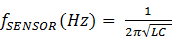
Figure 1-1 graphs several sensor frequency settings across capacitor and inductor values. For example, a 5-MHz sensor could use a 1-nF capacitor with an approximately 25-µH inductor. Refer to the Analog Wire blog post Inductive Sensing: Sensor frequency constraints for more information on how this graph is constructed.
 Figure 1-1 Sensor Frequency Versus Inductance and Capacitance
TI’s LDC devices work over a wide frequency range, from 1 kHz to 10 MHz for the LDC1312 family and LDC1612 family of devices. The LDC0851 can operate up to 19 MHz, and the LDC211x and LDC3114 can support a sensor frequency up to 30 MHz.
It is important to remember that the frequency of operation changes based on the position of the target. Typically, when the target is closest to the sensor, the sensor frequency is highest. The highest frequency cannot exceed the specified operation range for the LDC.