SLVAE30E February 2021 – March 2021 TPS1H000-Q1 , TPS1H100-Q1 , TPS1H200A-Q1 , TPS1HA08-Q1 , TPS25200-Q1 , TPS27S100 , TPS2H000-Q1 , TPS2H160-Q1 , TPS2HB16-Q1 , TPS2HB35-Q1 , TPS2HB50-Q1 , TPS4H000-Q1 , TPS4H160-Q1
- Trademarks
- 1Introduction
- 2Driving Resistive Loads
- 3Driving Capacitive Loads
- 4Driving Inductive Loads
- 5Driving LED Loads
- 6Appendix
- 7References
- 8Revision History
5.8 Constant Current Source
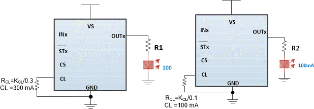
For the best LED performance it is best to use a constant current source, however often in systems with no LED drive module the only source available is a constant voltage source. Using a TI Smart High Side Switch a designer is able to create a constant current drive mode by forcing the device into current limit regulation mode. The current limiting feature is discussed more in depth in the capacitive driving section of this document in Section 3 as well as in the Adjustable Current Limit of Smart High Side Switches application note. The current limit threshold is set by an external resistor from the CL pin and should be chosen as equal to nominal LED current. Doing this ensures that the Smart High Side Switch will regulate the input voltage to provide a constant current source as long as the supply is capable of providing the power required. Figure 5-4 shows a switch in constant voltage mode on the left and a switch in constant current mode on the right.
 Figure 5-4 Driving LED in Constant Output Voltage and Constant Current Mode
On the left, the LED is nominally operated at 100 mA, but because it is regulated by the resistor that current will increase with an increasing supply voltage. On the right, if the supply voltage increases the switch will increase its resistance to maintain a 100 mA output current.
To operate the switch in constant current mode it must be ensured that the switch has enough room to regulate the source. For example, if the LED string consists of five LED's each with a 0.7-V drop and require 100-mA current (typical for a LED automotive interior light) then the total voltage over the string will be 3.5 V. If the minimum supply is 8 V then the resistor R2 should be chosen so that the supply can always supply 100 mA. In this case if R2 is less than 45 ohm then even at the minimum input supply voltage the LED string will still maintain 100 mA. When the supply is nominally at its value of 13.5 V the switch and the resistor will dissipate more heat to regulate the current flow as calculated in Equation 60. In this case the total DC dissipation should not cause thermal issues so the LEDs will be driven by the Smart High Side Switch creating a constant current source.

