SNLA113C november 2008 – june 2023 DS91M124 , DS91M125 , SN65LVDM050 , SN65LVDM050-Q1 , SN65LVDM051 , SN65LVDM051-Q1 , SN65LVDM1676 , SN65LVDM1677 , SN65LVDM176 , SN65LVDM179 , SN65LVDM180 , SN65LVDM22 , SN65LVDM31 , SN65MLVD040 , SN65MLVD047A , SN65MLVD048 , SN65MLVD080 , SN65MLVD082 , SN65MLVD128 , SN65MLVD129 , SN65MLVD2 , SN65MLVD200A , SN65MLVD202A , SN65MLVD204A , SN65MLVD204B , SN65MLVD206B , SN65MLVD3
- 1
- AN-1926 An Introduction to M-LVDS and Clock and Data Distribution Applications
- Trademarks
- 1 Introduction
- 2 M-LVDS Standard Overview
- 3 Driver Characteristics
- 4 Receiver Characteristics
- 5 M-LVDS Portfolio
- 6 M-LVDS Applications
- 7 Clock Distribution in AdvancedTCA Systems
- 8 Clock Distribution in MicroTCA Systems
- 9 M-LVDS as a Short Reach RS-485 Alternative
- 10Signal Distribution with Point-to-Point Links
- 11Wired-OR Implementation
- 12Design Guidelines
- 13Conclusion
- 14References
- 15Revision History
8 Clock Distribution in MicroTCA Systems
MicroTCA standard provides a modular, open platform for Low to Mid-range telecom and datacom equipment with capacity of up to 144 Gbps. MircoTCA systems are optimized for smaller physical sizes and more cost sensitive applications.
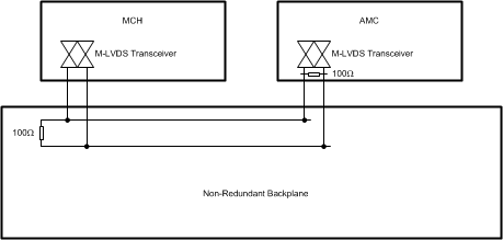
Similar to the ATCA standard, the MicroTCA (uTCA) standard also specifies the use of M-LVDS technology for clock distribution networks. The MicroTCA specification (PICMG MTCA.0) defines non-redundant and redundant clocking architectures. The non-redundant clocking architecture is for systems with a single MicroTCA Carrier Hub (MCH). This architecture allows up to three point-to-point links per Advanced Mezzanine Card (AMC) and up to 36 links per MCH. Figure 8-1 shows a single point-to-point clock link between a MCH and AMC in a non-redundant backplane. Note that the clock bus is terminated on the backplane at the MCH card and on the AMC card. In point-to-point links, M-LVDS device transmit clock signals with maximum noise margin.
 Figure 8-1 MicroTCA Non-redundant Clock
Distribution Interface Example
Figure 8-1 MicroTCA Non-redundant Clock
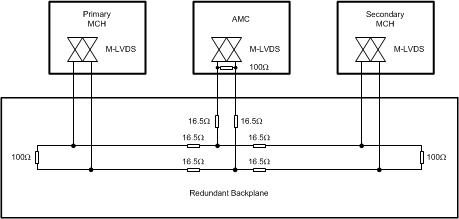
Distribution Interface ExampleThe redundant clock architecture is for dual MCH systems that operate in a redundant manner. In this clock architecture, each MCH connects to each AMC with a point-to-point link as in Figure 8-1. However, the connection between an AMC to each of the MCH cards is implemented with a multipoint network as illustrated in Figure 8-2. The effects of unterminated stubs in this multipoint topology variant are minimized with the use of series resistors. The controlled signal edges of M-LVDS devices further aid in distributing clocks to all cards within a system.
 Figure 8-2 MicroTCA Redundant Clock
Distribution Interface Example