SPRADB7 September 2023 AM2431 , AM2432 , AM2434 , AM2631 , AM2631-Q1 , AM2632 , AM2632-Q1 , AM2634 , AM2634-Q1 , AM263P2-Q1 , AM263P4 , AM263P4-Q1 , AM2732 , AM2732-Q1
- 1
- Abstract
- Trademarks
- 1Introduction
- 2Thermal Resistance Overview
- 3Board Design Choices that Affect Thermal Performance
- 4Thermal Design Best Practices Review
- 5AM263x EVM Thermal Comparison with Data
- 6Using the Thermal Model
- 7References
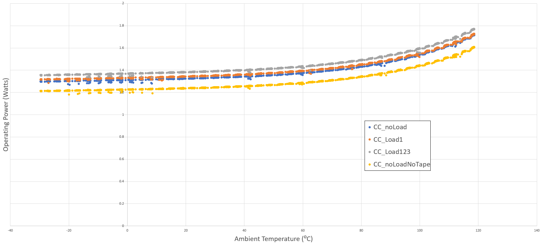
5.4.2 Power Readings over Temperature
The Operating Power was recorded during the measurements by polling the two INA228 power monitors for the 1.2 V and 3.3 V supply rail operating power. These two values were added together and then 125 mV was added to account for the VDDA supply rail operating power.
The operating power was recorded in four different configurations. The first three included Kapton tape on the package for lid temperature measurements. These three configurations included when only the logging script was run on R5_0 (CC_noLoad), the logging script run on R5_0 and R5_1 run at full load (CC_Load1), and the logging script run on R5_0 and R5_1/2/3 run at full load (CC_Load123). The final configuration for power measurement was when no Kapton tape was on top of the package, resulting in a noticeably decreased operating power due to the decreased thermal resistance between case temperature and ambient temperature or RΘCA.
| ThermalAir Airstream Output | Ambient Temperature Reading | CC_noLoadNoTape Power | CC_noLoad Power | CC_Load1 Power | CC_Load123 Power |
|---|---|---|---|---|---|
| -50℃ | -29.4 ℃ | 1.21 W | 1.30 W | 1.32 W | 1.36 W |
| 165℃ | 118.6 ℃ | 1.60 W | 1.71 W | 1.73 W | 1.77 W |
 Figure 5-5 AM263x Control Card Device
Operating Power Across Ambient Temperature Sweep