SPRADB7 September 2023 AM2431 , AM2432 , AM2434 , AM2631 , AM2631-Q1 , AM2632 , AM2632-Q1 , AM2634 , AM2634-Q1 , AM263P2-Q1 , AM263P4 , AM263P4-Q1 , AM2732 , AM2732-Q1
- 1
- Abstract
- Trademarks
- 1Introduction
- 2Thermal Resistance Overview
- 3Board Design Choices that Affect Thermal Performance
- 4Thermal Design Best Practices Review
- 5AM263x EVM Thermal Comparison with Data
- 6Using the Thermal Model
- 7References
5.2 Measurement Logging Software
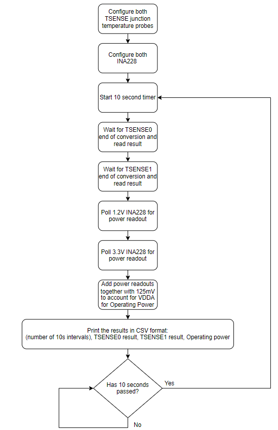
The following section serves to describe the measurement logging script that was run on the EVMs during the ambient temperature sweeps. Before the logging begins, the TSENSE internal junction temperature probes are configured.
In order to enable the temperature controller, the following bits need to be reset TMPSOFF, BGROFF, AIPOFF, and SNSR_MX_HIZ within the TOP_CTRL_TSENSE_CFG register. There are two internal temperature sensors (TSENSE0 and TSENSE1), each of which is located near the hotspots of the device. The SENSOR_SEL register controls the enabling of the individual sensors. For each selected sensor, the FSM requires anywhere between 51 to 54 clock cycles to start the sequences. Once the TSENSE_CFG_ENABLE bit is set, then the temperature measurement is initiated automatically. For more information on the thermal manager, see the Thermal Manager chapter within the AM263x Sitara™ Microcontrollers Technical Reference Manual.
The program makes use of the RTI timer module to start a 10 second timer between measurement readouts. For more information about the RTI timer module, see the Timer Modules chapter within the AM263x Sitara™ Microcontrollers Technical Reference Manual.
The AM263x Control Card features two INA228 power monitors for the 3.3 V and 1.2 V rail current measurements. The AM263x communicates with the INA228 power monitors through I2C commands. For further information on configuring the INA228 devices on the AM263x Control Card, see Monitoring Bus Voltage and Power Measurement on AM263x MCU Using INA226/INA228.
Section 5.2 shows the overview of the measurement recording program in a high-level flow diagram.
 Figure 5-2 Logging Software High-Level
Flow Diagram