SPRADB7 September 2023 AM2431 , AM2432 , AM2434 , AM2631 , AM2631-Q1 , AM2632 , AM2632-Q1 , AM2634 , AM2634-Q1 , AM263P2-Q1 , AM263P4 , AM263P4-Q1 , AM2732 , AM2732-Q1
- 1
- Abstract
- Trademarks
- 1Introduction
- 2Thermal Resistance Overview
- 3Board Design Choices that Affect Thermal Performance
- 4Thermal Design Best Practices Review
- 5AM263x EVM Thermal Comparison with Data
- 6Using the Thermal Model
- 7References
2.1 Junction Vs. Ambient Temperature
Before learning about the intricacies of thermal design, it is important to develop an understanding of the different temperatures of interest on a board. While the temperature on the package lid is what stands out on a thermal camera, the temperature beneath the lid is what determines the functionality of the device. Specifically, the area near hotspots on the die or junction temperature (TJ). Junction temperature is influenced by many things but there is a clear relationship between the junction temperature and the temperature of the free air surrounding a system or ambient temperature (TA). This relationship between junction temperature and ambient temperature can be defined by the thermal characteristic: RΘJA or the thermal resistance between junction and ambient temperature.
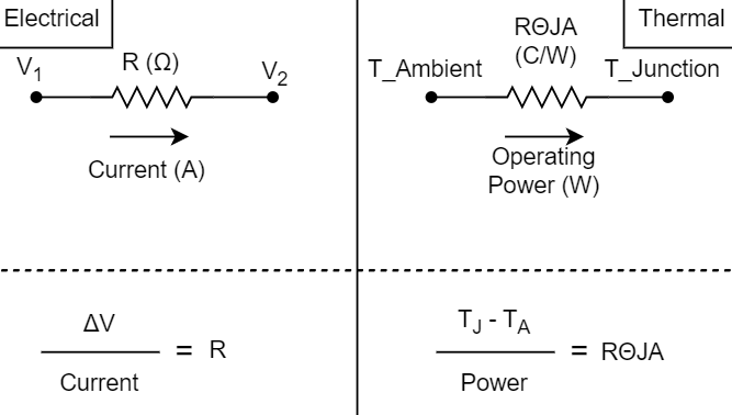
Thermal properties can be represented similarly to a simple electrical circuit. From this perspective, "Ohm's law" still applies to the thermal "circuit". The operating power of the device in Watts is analogous to the current of the circuit and the thermal resistance between the two temperatures is the resistance.
 Figure 2-1 Electrical vs Thermal Nodal
Analysis
Figure 2-1 Electrical vs Thermal Nodal
AnalysisThe AM263x Sitara™ Microcontrollers Data Sheet lists values for thermal resistance characteristics but these values do not always tell the whole story. The thermal resistance characteristics in the data sheet are based upon a specific test condition based on a Joint Electron Device Engineering Council (JEDEC) defined 2S2P system.