SPRADB7 September 2023 AM2431 , AM2432 , AM2434 , AM2631 , AM2631-Q1 , AM2632 , AM2632-Q1 , AM2634 , AM2634-Q1 , AM263P2-Q1 , AM263P4 , AM263P4-Q1 , AM2732 , AM2732-Q1
- 1
- Abstract
- Trademarks
- 1Introduction
- 2Thermal Resistance Overview
- 3Board Design Choices that Affect Thermal Performance
- 4Thermal Design Best Practices Review
- 5AM263x EVM Thermal Comparison with Data
- 6Using the Thermal Model
- 7References
5.1 Test Setup and Materials
The materials used for this thermal measurement procedure are as follows:
- MPI Thermal ThermalAir TA-5000A
Precise Temperature Forcing System
- Constant flow of air to control the ambient temperature within the enclosure
- Two National Instruments USB-TC01
Temperature Input Devices
- Used to record data for the ambient temperature and AM263x lid temperature over time
- Two Type-T thermocouple probes
- Type-T thermocouple temperature probes have an accurate temperature range of -185℃ to 300℃
- Sealed acrylic thermal chamber
- Allows for ambient temperature to be manipulated by the ThermalAir system
- AM263x Control Card Evaluation Module
- AM263x LaunchPad Evaluation Module
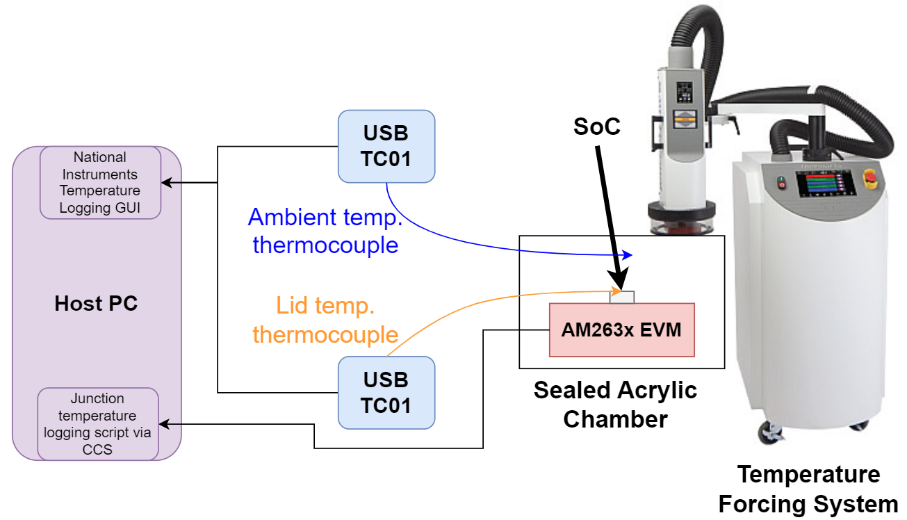
 Figure 5-1 Testing Setup Diagram
To conduct the thermal measurements, the Evaluation module is placed within the acrylic thermal enclosure such that it is under the air vent of the ThermalAir system. One of the thermocouple probes is placed onto the middle of the AM263x device package lid and secured using Kapton tape. The other probe is secured to the EVM with Kapton tape above the board to record the ambient temperature of the system. Both thermocouple probes are connected to a NI USB-TC01 device to record the thermal measurements. The USB-TC01 devices are programmed to log the temperature of the connected probe every ten seconds.
The ThermalAir system allows for control of the air flow rate and temperature. For these measurements, the flow rate of air is set to 12.0 standard cubic feet per minute (SCFM). There is a script that is used to configure the temperature of the air stream from the ThermalAir nozzle output. The script increments the temperature of the air flow by 5℃ every 10 minutes where the temperature starts at -50℃ and ends at 165℃. It should be noted that the ambient temperature within the enclosure will not be the same as the air flow temperature. Before the script begins, the ThermalAir is set to output -50℃ air until the enclosure reaches a steady ambient temperature at approximately -30℃.
The Evaluation Modules make use of two different programs that will be run on the R5 cores. The first program is loaded onto R5F_0 and it is responsible for logging the internal junction temperature every ten seconds. The second program is loaded onto cores to simulate a full load on that particular core. The measurements taken in this procedure include when just the logging script is running on R5F_0, when the logging script is running on R5F_0 and R5F_1 is at full load, and when the logging script is running on R5F_0 and R5_1/2/3 are all at full load. The AM263x Control Card is designed with the INA228 power monitor that allows the operating power to be recorded every ten seconds in addition to the junction temperature recordings so that the power consumption can be observed over different values of junction temperature and ambient temperature. The AM263x LaunchPad does not have the INA228 power monitor and these values were not recorded for this EVM.
As with any test environment, there are variables that must be considered. The EVMs and temperature probes were not moved during the course of the three tests on each EVM but there were differences in the test setup for the LaunchPad and Control Card. The position of the temperature probes and EVM itself were approximately in the same position in relation to the air stream nozzle but not in the same exact position. Additionally, since these tests were taken over the course of many days, the temperature of the lab was not constant and has a small impact on the ambient temperature readings within the enclosure.