SPRADB7 September 2023 AM2431 , AM2432 , AM2434 , AM2631 , AM2631-Q1 , AM2632 , AM2632-Q1 , AM2634 , AM2634-Q1 , AM263P2-Q1 , AM263P4 , AM263P4-Q1 , AM2732 , AM2732-Q1
- 1
- Abstract
- Trademarks
- 1Introduction
- 2Thermal Resistance Overview
- 3Board Design Choices that Affect Thermal Performance
- 4Thermal Design Best Practices Review
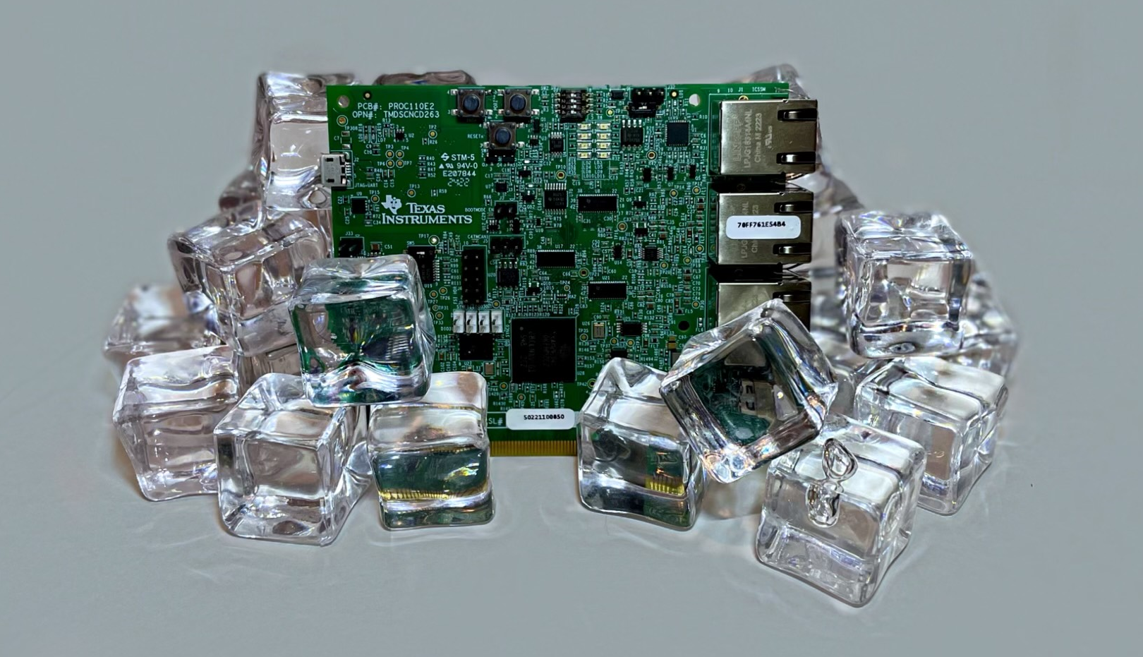
- 5AM263x EVM Thermal Comparison with Data
- 6Using the Thermal Model
- 7References
Abstract
Temperature, both internal and external to the package, can have a great influence on the characteristics of a device. The temperature of the die within the package can affect both the functionality and reliability of a device. Device packages can also become too hot and present a safety concern to users. All of these reasons and more are why the thermal properties of a printed circuit board should be heavily reviewed. Whether it is copper thickness or layer count, there are many different aspects of the PCB design that affect the thermal characteristics of the board. This document will describe many best practices and rules of thumb when it comes to thermal dissipation in PCB design. The in-depth discussion will then be put to the test through a real-world experiment that measures the junction temperature of two different AM263x evaluation modules (EVMs). The results of the experiment will be reviewed and justify how the different thermal design choices that were made in both EVMs affected the thermal performance.