SPRUJ12F August 2021 – January 2024 AM2431 , AM2432 , AM2434
- 1
- Abstract
- Trademarks
- 1Preface: Read This First
- 2Kit Overview
- 3Board Setup
-
4Hardware Description
- 4.1 Functional Block Diagram
- 4.2 BoosterPack Headers
- 4.3 GPIO Mapping
- 4.4 Reset
- 4.5 Clock
- 4.6 Memory Interface
- 4.7 Ethernet Interface
- 4.8 USB 2.0 Interface
- 4.9 I2C Interface
- 4.10 Industrial Application LEDs
- 4.11 UART Interface
- 4.12 eQEP Interface
- 4.13 CAN Interface
- 4.14 FSI Interface
- 4.15 JTAG Emulation
- 4.16 Test Automation Interface
- 4.17 SPI Interface
- 5References
- A E3 Design Changes
- B Revision A Design Changes
- Revision History
3.3 Boot Mode Selection
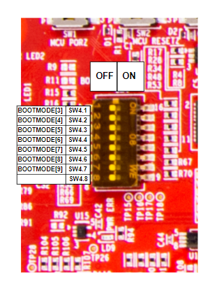
BOOTMODE[9:3] for the AM243x are selected by a DIP switch (SW4) or the test automation header. The remaining BOOTMODE[2:0] and BOOTMODE[12:10] are selected through the use of resistors. The test automation header uses an I2C IO expansion buffer to drive the bootmode when PORz is toggled. For more details about the test automation header, see Section 4.16. The supported boot modes are as follows:
- QSPI
- MMC - μSDCard (no direct support)
- Universal asynchronous receiver/transmitter (UART)
- USB-DFU
- No-boot
Table 3-4 Boot-Mode Selection Table
| Boot Modes Supported | SW4.1 | SW4.2 | SW4.3 | SW4.4 | SW4.5 | SW4.6 | SW4.7 |
|---|---|---|---|---|---|---|---|
| QSPI Flash | 0 | 1 | 0 | 0 | 0 | 1 | 0 |
| MMC1/SD Card | 0 | 0 | 0 | 1 | 0 | 0 | 1 |
| UART | 1 | 1 | 1 | 0 | 0 | 0 | 0 |
| USB -DFU | 0 | 1 | 0 | 1 | 0 | 0 | 0 |
| No Boot | 1 | 1 | 1 | 1 | 0 | 0 | 0 |
 Figure 3-7 Boot-Mode DIP Switch
Note: SW4.8 of the DIP switch remains
unused.