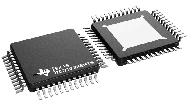
Gehäuseinformationen
| Gehäuse | Pins HTQFP (PHP) | 48 |
| Betriebstemperaturbereich (°C) -40 to 105 |
| Gehäusemenge | Träger 250 | SMALL T&R |
Merkmale von TPS65218D0
- Three Adjustable Step-Down Converters With Integrated Switching FETs (DCDC1,
DCDC2, DCDC3):
- DCDC1: 1.1-V Default, up to 1.8 A
- DCDC2: 1.1-V Default, up to 1.8 A
- DCDC3: 1.2-V Default, up to 1.8 A
- VIN Range From 2.7 V to 5.5 V
- Adjustable Output Voltage Range 0.85 V to 1.675 V (DCDC1 and DCDC2)
- Adjustable Output Voltage Range 0.9 V to 3.4 V (DCDC3)
- Power Save Mode at Light Load Current
- 100% Duty Cycle for Lowest Dropout
- Active Output-Discharge When Disabled
- One Adjustable Buck-Boost Converter With Integrated
Switching FETs (DCDC4):
- DCDC4: 3.3 V Default, up to 1.6 A
- VIN Range From 2.7 V to 5.5 V
- Adjustable Output Voltage Range 1.175 V to 3.4 V
- Active Output-Discharge When Disabled
- Two
Low-Quiescent Current, High Efficiency Step-Down Converters for Battery Backup Domain (DCDC5,
DCDC6)
- DCDC5: 1-V Output
- DCDC6: 1.8-V Output
- VIN Range from 2.2 V to 5.5 V
- Supplied From System Power or Coin-Cell Backup Battery
- Adjustable General-Purpose LDO (LDO1)
- LDO1: 1.8-V Default up to 400 mA
- VIN Range From 1.8 V to 5.5 V
- Adjustable Output Voltage Range From 0.9 V to 3.4 V
- Active Output-Discharge When Disabled
- Low-Voltage Load Switch (LS1) With 350-mA
Current Limit
- VIN Range From 1.2 V to 3.6 V
- 110-mΩ (Max) Switch Impedance at 1.35 V
- 5-V Load Switch
(LS2) With 100-mA or 500-mA Selectable Current Limit
- VIN Range From 3 V to 5.5 V
- 500-mΩ (Max) Switch Impedance at 5 V
- High-Voltage Load Switch (LS3) With 100-mA or
500-mA Selectable Current Limit
- VIN Range From 1.8 V to 10 V
- 500-mΩ (Max) Switch Impedance
- Supervisor With Built-in Supervisor Function Monitors
- DCDC1, DCDC2 ±4% Tolerance
- DCDC3, DCDC4 ±5% Tolerance
- LDO1 ±5% Tolerance
- Protection, Diagnostics, and Control:
- Undervoltage Lockout (UVLO)
- Always-on Push-Button Monitor
- Overtemperature Warning and Shutdown
- Separate Power-Good Output for Backup and Main Supplies
- I2C Interface (Address 0x24) (See Timing Requirements for I2C Operation at 400 kHz)
Beschreibung von TPS65218D0
The TPS65218D0 is a single chip, power-management IC (PMIC) specifically designed to support the AM335x and AM438x line of processors in both portable (Li-Ion battery) and nonportable (5-V adapter) applications. The device is characterized across a –40°C to +105°C temperature range, making it suitable for various industrial applications.
The TPS65218D0 is specifically designed to provide power management for all the functionalities of the AM438x processor. The DC/DC converters DCDC1 through DCDC4 are intended to power the core, MPU, DDR memory, and 3.3-V analog and I/O, respectively. LDO1 provides the 1.8-V analog and I/O for the processor. GPIO1 and GPO2 allow for memory reset and GPIO3 allows for warm reset (335x only) of the DCDC1 and DCDC2 converters. The I2C interface allows the user to enable and disable all voltage regulators, load switches, and GPIOs. Additionally, UVLO and supervisor voltage thresholds, power-up sequence, and power-down sequence can be programmed through I2C. Interrupts for overtemperature, overcurrent, and undervoltage can be monitored as well. The supervisor monitors DCDC1 through DCDC4 and LDO1. The supervisor has two settings, one for typical undervoltage tolerance (STRICT = 0b), and one for tight undervoltage and overvoltage tolerances (STRICT = 1b). A power-good signal indicates proper regulation of the five voltage regulators.
Three hysteretic step-down converters are targeted at providing power for the processor core, MPU, and DDRx memory. The default output voltages for each converter can be adjusted through the I2C interface. DCDC1 and DCDC2 feature dynamic voltage scaling to provide power at all operating points of the processor. DCDC1 and DCDC2 also have programmable slew rates to help protect processor components. DCDC3 remains powered while the processor is in a sleep mode to maintain power to DDRx memory. Backup power provides two step-down converters for the tamper, RTC, or both domains of the processor if system power fails or is disabled. If both system power and coin-cell battery are connected to the PMIC, power is not drawn from the coin-cell battery. A separate power good signal monitors the backup converters. A battery backup monitor determines the power level of the coin-cell battery.
The TPS65218D0 device is available in a 48-pin VQFN package (6 mm × 6 mm, 0.4-mm pitch).
