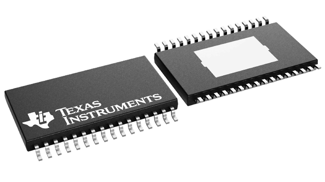
Gehäuseinformationen
| Gehäuse | Pins HTSSOP (DAP) | 32 |
| Betriebstemperaturbereich (°C) -40 to 125 |
| Gehäusemenge | Träger 250 | SMALL T&R |
Merkmale von TPS65381A-Q1
- Qualified for Automotive Applications
- AEC-Q100 Qualified With the
Following Results:
- Device Temperature Grade 1: –40°C to +125°C Ambient Operating Temperature
- Device HBM ESD Classification Level H2
- Device CDM ESD Classification Level C3B
- Multirail Power
Supply Supporting Among Others
- TI Hercules™ TMS570, C2000™, and Various Functional-Safety Architecture Microcontrollers
- Supply Rails
- Input voltage range:
- 5.8 V to 36 V (CAN, I/O, MCU Core, and Sensor-Supply Regulators Functional)
- 4.5 V to 5.8 V (3.3 V I/O and MCU Core Regulators Functional)
- 6-V Asynchronous Switch Mode Preregulator With Internal FET, 1.3-A Output Current
- 5-V (CAN) Supply Voltage, Linear Regulator With Internal FET, 300-mA Output Current
- 3.3-V or 5-V (MCU I/O) Voltage, Linear Regulator With Internal FET, 300-mA Output Current
- 0.8-V to 3.3-V Adjustable (MCU Core Voltage), Linear Regulator Controller With External FET
- 3.3-V to 9.5-V Adjustable Sensor Supply: Linear Tracking Regulator With Internal FET, 100-mA Output Current, and Protection Against Short-to-Supply and Short-to-Ground
- Charge Pump: Typically 12 V Above Battery Voltage
- Input voltage range:
- Power Supply and System Monitoring
- Independent Undervoltage and Overvoltage Monitoring on All Regulator Outputs, Battery Voltage, and Internal Supplies
- Independent Voltage References for Regulator References and Voltage Monitoring. Voltage-Monitoring Circuitry With Independent Bandgap Reference and Separate Supply Input Pin
- Self-Check on all Voltage Monitoring (Automatic During Power-Up and After Power-Up Initiated by External MCU)
- All Supplies With Internal FETs Protected With Current-Limit and Overtemperature Shutdown
- Microcontroller (MCU) Interface
- Watchdog: Trigger Mode (OPEN/CLOSE Window) or Question and Answer Mode
- MCU Error-Signal Monitor For Lock-Step Dual-Core MCUs Including Hercules™ TMS570, C2000™, and Various Functional-Safety Architecture MCUs Using Pulse-Width Modulation (PWM) Error Output
- DIAGNOSTIC State for Performing Device Self-Tests, Diagnostics, and External Interconnect Checks
- SAFE State for Device and System Protection on Error Event Detection
- Clock Monitor for Internal Oscillator
- Self-Tests for Analog- and Digital-Critical Circuits Executed With Every Device Power Up or Activated by MCU in DIAGNOSTIC State
- CRC on Nonvolatile Memory, Device and Configuration Registers
- Reset Circuit and Output Pin for MCU
- Diagnostic Output Pin Allowing MCU to Observe Through a Multiplexer Internal Analog and Digital Signals of the Device
- Serial
Peripheral Interface (SPI)
- Configuration Registers
- Watchdog Question and Answers
- Diagnostic Status Readout
- Compliant With 3.3-V and 5-V Logic Levels
- Enable Drive Output for Disabling Safing-Path or External Power-Stages on Detected System-Failure
- Wakeup Through IGNITION Pin or CAN WAKEUP Pin
- Package: 32-Pin HTSSOP PowerPAD™ IC Package
Beschreibung von TPS65381A-Q1
The TPS65381A-Q1 device is a multirail power supply designed to supply microcontrollers (MCUs) in safety-relevant applications, such as those found in automotive and industrial markets. The device supports Texas Instruments’ Hercules™ TMS570 MCU and C2000™ MCU families, and various other MCUs with dual-core lockstep (LS) or loosely-coupled architectures (LC).
The TPS65381A-Q1 device integrates multiple supply rails to power the MCU, controller area network (CAN), or FlexRay, and an external sensor. An asynchronous-buck switch-mode power-supply converter with an internal FET converts the input supply (battery) voltage to a 6-V preregulator output. This 6-V preregulator supplies the other regulators. The device supports wakeup from IGNITION or wakeup from the CAN transceiver.
The integrated, fixed 5-V linear regulator with internal FET can be used for a CAN or FlexRay transceiver supply for example. A second linear regulator, also with an internal FET, regulates to a selectable 5-V or 3.3-V output which, for example, can be use for the MCU I/O voltage.
The TPS65381A-Q1 device includes an adjustable linear-regulator controller, requiring an external FET and resistor divider, that regulates to an adjustable voltage of between 0.8 V and 3.3 V which may be used for the MCU core supply.
The integrated sensor supply can be run in tracking mode or adjustable output mode and includes short-to-ground and short-to-battery protection. Therefore, this regulator can power a sensor outside the module or electronic control unit (ECU).
The integrated charge pump provides overdrive voltage for the internal regulators. The charge pump can also be used in a reverse-battery protection circuit by using the charge-pump output to control an external NMOS transistor. This solution allows for a lower minimum-battery-voltage operation compared to a traditional reverse-battery blocking diode when the device must be operational at the lowest possible supply voltages.
The device monitors undervoltage and overvoltage on all regulator outputs, battery voltage, and internal supply rails. A second bandgap reference, independent from the main bandgap reference, is used for the undervoltage and overvoltage monitoring, to avoid any drifts in the main bandgap reference from being undetected. In addition, regulator current-limits and temperature protections are implemented.
The TPS65381A-Q1 device has monitoring and protection functions, which include the following: watchdog with trigger and question and answer modes, MCU error-signal monitor, clock monitoring on internal oscillators, self-check on the clock monitor, cyclic redundancy check (CRC) on nonvolatile memory, a diagnostic output pin allowing the MCU to observe internal analog and digital signals of the device, a reset circuit and output pin for the MCU, and an enable drive output to disable the safing-path or external-power stages on detected faults. A built-in self-test (BIST) monitors the device functionality automatically at power-up. A dedicated DIAGNOSTIC state allows the MCU to check TPS65381A-Q1 monitoring and protection functions.
The TPS65381A-Q1 device is offered in a 32-pin HTSSOP PowerPAD package.
