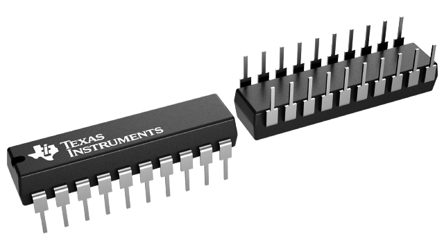
Gehäuseinformationen
| Gehäuse | Pins PDIP (N) | 20 |
| Betriebstemperaturbereich (°C) -40 to 105 |
| Gehäusemenge | Träger 18 | TUBE |
Merkmale von UCC28511
- Provides Control of PFC and PWM Power Stages In One Device
- Leading-Edge PFC, Trailing-Edge PWM Modulation for Reduced Ripple
- Built-In Sequencing of PFC and PWM Turn-On
- 2-A Source and 3-A Sink Gate Drive for Both PFC and PWM Stages
- Typical 16-ns Rise Time and 7-ns Fall Time into 1-nF Loads
- PFC Features
- Average-Current-Mode Control for Continuous Conduction Mode Operation
- Highly-Linear Multiplier for Near-Unity Power Factor
- Input Voltage Feedforward Implementation
- Improved Load Transient Response
- Accurate Power Limiting
- Zero Power Detect
- PWM Features
- Peak-Current-Mode Control Operation
- 1:1 or 1:2 PFC:PWM Frequency Options
- Programmable maximum duty cycle
- Programmable Soft-Start
- Two Hysteresis Options for Differing Hold-Up Time Requirements
Beschreibung von UCC28511
The UCC28510 series of combination PFC/PWM controllers provide complete control functionality for any off-line power system requiring compliance with the IEC1000–3–2 harmonic reduction requirements. By combining the control and drive signals for the PFC and the PWM stages into a single device, significant performance and cost benefits are gained. By managing the modulation mechanisms of the two stages (leading-edge modulation for PFC and trailing-edge modulation for PWM), the ripple current in the boost capacitor is minimized.
Based on the average current mode control architecture with input voltage feedforward of prior PFC/PWM combination controllers, these devices offer performance advantages. Two new key PWM features are programmable maximum duty cycle and the 2x PWM frequency options to the base PFC frequency. For the PFC stage, the devices feature an improved multiplier and the use of a transconductance amplifier for enhanced transient response.
The core of the PFC section is in a three-input multiplier that generates the reference signal for the line current. The UCC28510 series features a highly linearized multiplier circuit capable of producing a low distortion reference for the line current over the full range of line and load conditions. A low-offset, high-bandwidth current error amplifier ensures that the actual inductor current (sensed through a resistor in the return path) follows the multiplier output command signal. The output voltage error is processed through a transconductance voltage amplifier.
The transient response of the circuit is enhanced by allowing a much faster charge/discharge of the voltage amplifier output capacitance when the output voltage falls outside a certain regulation window. A number of additional features such as UVLO circuit with selectable hysteresis levels, an accurate reference voltage for the voltage amplifier, zero power detect, OVP/enable, peak current limit, power limiting, high-current output gate driver characterize the PFC section.
The PWM section features peak current mode control (with a ramp signal available to add slope compensation), programmable soft-start, accurate maximum duty cycle clamp, peak current limit and high-current output gate driver. The oscillator for the combination controller is available in two versions. In UCC28510, UCC28511, UCC28512, and UCC28513, the PWM and the PFC circuits are switched at the same frequency. In the UCC28514, UCC28515, UCC28516, and UCC28517, the PWM stage frequency is twice that of the PFC frequency. The PWM stage is suppressed until the PFC output has reached 90% of its programmed value during startup. During line dropout and turn off, the device allows the PWM stage to operate until the PFC output has dropped to 47% (UCC28512, UCC28513, UCC28516, and UCC28517) or 71% (UCC28510, UCC28511, UCC28514, and UCC28515) of its nominal value. See available options table on page 1 for a summary of options.
The UCC28510 family also features leading-edge modulation for the PFC stage and trailing-edge modulation for the PWM stage in order to reduce the ripple current in the boost output capacitor. The current amplifier implementation associated with this scheme also results in better noise immunity.
Available in 20-pin N and DW packages.
