DLPU101C december 2020 – may 2023 DLPC900
- 1
- 1 Trademarks
- Read This First
- 2 About This Guide
- 3 Related Documentation from Texas Instruments
- 4 If You Need Assistance
- 5 DLP LightCrafter Single DLPC900 EVM Overview
- 6 Quick Start
-
7 Operating the
DLP LightCrafter Single DLPC900 EVM
- 7.1 DLP LightCrafter Single DLPC900 Control Software
- 7.2 PC Software
- 7.3 System Common Controls
- 7.4 System Settings
- 7.5 Video Mode
- 7.6
Pattern Modes
- 7.6.1 Menu Bar
- 7.6.2 Creating a Pattern Sequence in Pattern On-The-Fly Mode
- 7.6.3 Creating a Pattern Sequence in Pre-Stored Pattern Mode
- 7.6.4 Reordering a Pattern Sequence using the Edit LUT Feature
- 7.6.5 Creating a Pattern Sequence in Video Pattern Mode
- 7.6.6 Creating a Pattern Sequence With DMD Block Load
- 7.6.7 Pattern Settings
- 7.7 Batch Files
- 7.8 Peripherals
- 7.9 Firmware
- 7.10 Flash Device Parameters
- 7.11 JTAG Flash Programming
- 7.12 Programming an EDID
- 8 Connectors
- 9 Power Supply Requirements
- 10Safety
- 11Revision History
7.5 Video Mode
Click the Video Mode button at the top of the GUI to display the Video Mode panel. Within this panel, there are two tabs:
- The Source Settings Tab is shown in Figure 7-4.
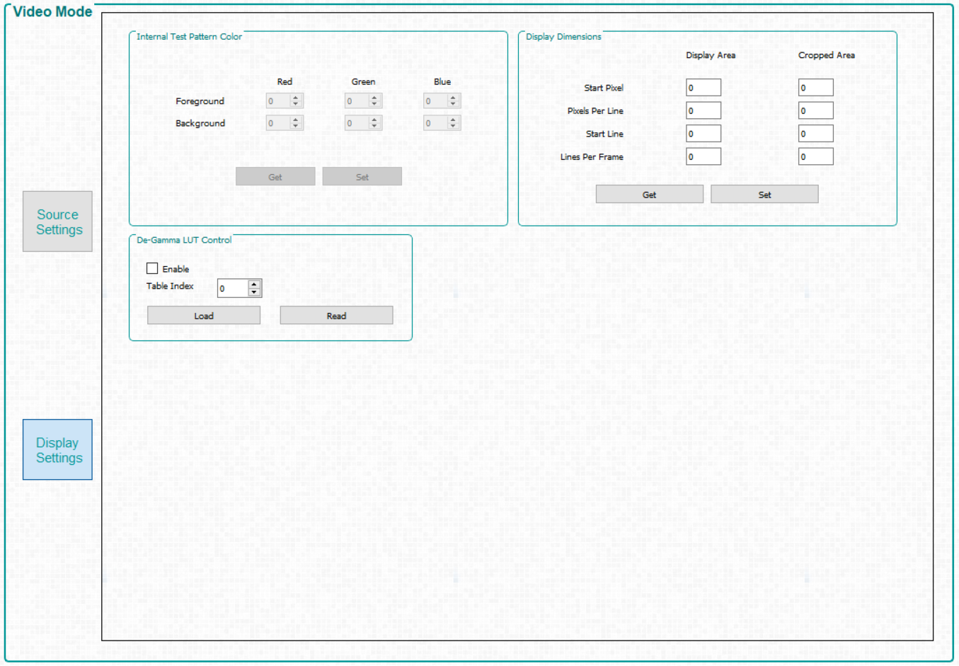
- The Display Settings Tab is shown in Video Mode Panel - Display Settings Tab.
 Figure 7-4 Video
Mode Panel - Source Settings Tab
Figure 7-4 Video
Mode Panel - Source Settings Tab- Input Configuration.
- Source Select –
Allows the user to select :
- Parallel RGB interface
- Internal test pattern generator
- Pattern images from flash memory
- Solid Curtain– which displays a constant, solid color image (including black or white)
- Input Port Data Swap – Depending on the routing of the parallel RGB data lines, it may be necessary to swap the order of the color channels. The DLP LightCrafter Single DLPC900 EVM requires an RGB → GRB setting. The user selects which port to apply the settings.
- Pixel Data Format – Allows the user to select the video format of the input source.
- Source Select –
Allows the user to select :
- Port Config Controls –
Depending on which input signals were chosen during board design, it may be
necessary to select the appropriate signals so that the DLPC900 can properly
detect the incoming video source. If incorrect settings are chosen, the curtain
may be displayed or the image may be incorrect. Pixel Mode can also be
set to Single Pixel or Dual Pixel. Dual Pixel allows for higher data rates by
loading two pixels per clock instead of one pixel per clock.Note: Only Pixel Clock 1 is connected on the DLPLCRC900EVM. Selecting Pixel Clock 2 or 3 on the EVM will result in erratic behavior.
- IT6535 Receiver – This control allows selection between the HDMI or the DisplayPort input connectors of the IT6535 digital receiver. The digital receiver can also be powered-down, which tri-states all the output signals of the IT6535 to allow another device to share the input ports and syncs of the DLPC900.
- Parallel Port Configuration - Allows readback of the current parallel port configuration parameters determined by the EDID or user Display Dimensions. Values are read only from the primary controller.
 Figure 7-5 Video
Mode Panel - Display Settings Tab
Figure 7-5 Video
Mode Panel - Display Settings Tab- Internal Test Pattern Color – When the internal test pattern is selected as the input source, the foreground and background colors can be changed.
- Display Dimensions – Allows the user to scale or crop the image of the incoming video source.
- De-Gamma LUT Control –
De-Gamma controls:
- Enable/Disable - Command enables or disables De-Gamma
- Sets the level of De-gamma - See the Gamma Configuration and Enable section of the DLPC900 Programmer's Guide for further information