SPRADE9 November 2023 AM2431 , AM2432 , AM2434 , AM623 , AM625 , AM625-Q1 , AM625SIP , AM62A1-Q1 , AM62A3 , AM62A3-Q1 , AM62A7 , AM62A7-Q1 , AM62P-Q1 , AM6411 , AM6412 , AM6421 , AM6422 , AM6441 , AM6442 , AM6526 , AM6528 , AM6546 , AM6548 , AM67 , AM67A , AM68 , AM68A , AM69 , AM69A , DRA821U , DRA821U-Q1 , DRA829J , DRA829J-Q1 , DRA829V , DRA829V-Q1
2.1 Overview
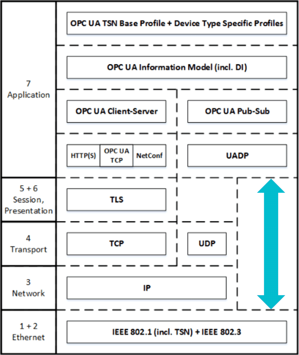
An application level protocol like PROFINET or OPC UA is used above TSN capable Ethernet with or without transport and session level protocols like IP and UDP. Figure 2-1 shows an example of OPC UA and the networking layers. EtherCAT is always directly over Ethernet, shown as the blue arrow line for OPC UA Pub-Sub in Figure 2-1, with only the controller (Main) initiating the sending of a frame. The local area network (LAN) only has frames of the EtherType reserved for EtherCAT, sent by the Main or the last Subordinate in the line topology.
 Figure 2-1 OPC UA Over TSN With Blue Line
Indicating OPC UA Pub-Sub
Figure 2-1 OPC UA Over TSN With Blue Line
Indicating OPC UA Pub-SubNetworking software stacks have successfully leveraged the layered model shown in Figure 2-2 for decades. While great for adding features and scalability, the drawback for real-time control is worst-case latency. This is where industrial protocols prioritize timeliness or managed latency over everything else, in practice bypassing the networking stack and sometimes even the Ethernet driver.
 Figure 2-2 Networking Software Stack
Distributed real-time control applications typically use the concept of a cycle. The control application reads inputs, does computation on what the next desired state is, and then sends those outputs out. With industrial Ethernet the inputs and outputs are distributed over the network. This can be visualized in a timing diagram as shown in Figure 2-3. The gray part, labeled “App. Task”, is the time consumed by the application in each cycle. Since input and output communication are processes that consume application task processing time in the cycle period, the overhead of input and output communication needs to be budgeted. This budget is based on the worst-case for both compute and communication jitter.
![Time View of Cyclic Control
[5] GUID-20231011-SS0I-F955-21FJ-GBXGG4PTSZ9L-low.png](/ods/images/SPRADE9/GUID-20231011-SS0I-F955-21FJ-GBXGG4PTSZ9L-low.png) Figure 2-3 Time View of Cyclic Control
[5]
Figure 2-3 Time View of Cyclic Control
[5]In addition to the communication of inputs and outputs, an industrial communication protocol provides the distributed devices with synchronization, or a common view of time. The accuracy of synchronization is often directly relevant to the application, regardless of cycle time or compute needs. For instance, synchronization jitter at the microsecond level or even down to the sub-100 nanosecond level across a distributed system is often critical for a cyber-physical system. However, in the communication of inputs and outputs, the system can tolerate microsecond or even tens-of-microseconds level jitter. The cost of this jitter is reduced application computation time in each cycle.