SLVA680A February 2015 – April 2022 ESD401 , TPD12S015 , TPD12S015A , TPD12S016 , TPD12S520 , TPD12S521 , TPD13S523 , TPD1E05U06 , TPD1E10B06 , TPD1E10B09 , TPD1S414 , TPD1S514 , TPD2E001 , TPD2E001-Q1 , TPD2E009 , TPD2E1B06 , TPD2E2U06-Q1 , TPD2EUSB30 , TPD2S017 , TPD3S014 , TPD3S044 , TPD4E001-Q1 , TPD4E004 , TPD4E02B04 , TPD4E05U06 , TPD4E05U06-Q1 , TPD4E101 , TPD4E1U06 , TPD4E6B06 , TPD4EUSB30 , TPD4F202 , TPD4S010 , TPD4S014 , TPD4S1394 , TPD4S214 , TPD5S115 , TPD5S116 , TPD6E004 , TPD6E05U06 , TPD6F002-Q1 , TPD6F003 , TPD6F202 , TPD7S019 , TPD8E003 , TPD8F003
2.1 Optimizing Impedance for Dissipating ESD
Outside of controlled RLC values, PCBs have inherent parasitics which contribute to overall board performance. Usually these parasitics are detrimental to the functionality of the design. An important parasitic to consider when designing a circuit to dissipate ESD is inductance. Because (see Note 1, below) VESD = Vbr_TVS + RDYN(TVS)IESD + L(dIESD/dt), and the term dIESD/dt is very large, the forced current in an ESD event will cause large voltages to drop across any inductance. For example, in an 8 kV ESD event as specified by IEC 61000-4-2, the dIESD/dt = (30 A)/(0.8×10-9 s) = 4 × 10¹⁰ A/s. So even with 0.25 nH of inductance an additional 10 V is presented to the system.
- Vbr_TVS is the voltage required for the TVS to enter its breakdown region and begin shunting IESD to ground.
- RDYN(TVS) refers to the resistance through the TVS diode array while operating in the breakdown region of the IV curve.
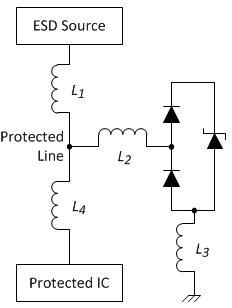
 Figure 2-1 PCB Inductance around a Single-channel TVS
In Figure 2-1 four parasitic inductors are shown: L1 and L2 is the inductance in the circuit between the ESD Source (typically a connector) and the TVS, L3 is the inductance between the TVS and ground, and L4 is the inductance between the TVS and the Protected IC. Not considering VIAs, the inductors L1 and L4 are generally dependant upon design constraints such as impedance controlled signal lines. However, IESD can still be "steered" towards the TVS by making L4 much larger than L1. This is accomplished by placing the TVS as near to the ESD Source as the PCB design rules allow while placing the Protected IC far away from the TVS, for example near the middle of the PCB. This effectively creates L4 >> L1, helping shunt the IESD to the TVS. Placing the TVS adjacent to the connector also mitigates EMI from radiating into the system. The inductor shown at L2 should not be present in a well designed system. This represents a stub between the TVS and the line being protected. This design practice should be avoided. The Protected Line should run directly from the ESD Source to the protection Pin of the TVS, ideally with no VIAs in the path. The inductor at L3 represents the inductance between the TVS and ground. This value should be reduced as much as possible, and perhaps represents the most predominant parasitic influencing VESD. The voltage presented to the node "Protected Line" will be VESD = Vbr_TVS + IESDRDYN(TVS) + (L2 + L3)(dIESD/dt). Thus the PCB designer needs to minimize L3 and eliminate L2. Minimizing L3 is covered in Section 2.4. Minimizing L1 is covered in Section 2.2 and Section 2.3.
Summary
- Minimize any inductance between the ESD Source and the path to ground through the TVS
- Place the TVS as near to the connector as design rules allow
- Place the Protected IC much further from the TVS than the TVS is to the connector
- Do not use stubs between the TVS and the Protected Line, route directly from the ESD Source to the TVS
- Minimizing inductance between the TVS and ground is critical