SPRAAR7J November 2018 – February 2023 66AK2G12 , AM1806 , AM1808 , AM2431 , AM2432 , AM2434 , AM3351 , AM3352 , AM3354 , AM3356 , AM3357 , AM3358 , AM3358-EP , AM3359 , AM3871 , AM3874 , AM3892 , AM3894 , AM4376 , AM4377 , AM4378 , AM4379 , AM5706 , AM5708 , AM5716 , AM5718 , AM5726 , AM5728 , AM5729 , AM5746 , AM5748 , AM5749 , AM620-Q1 , AM623 , AM625 , AM625-Q1 , AM625SIP , AM62A3 , AM62A3-Q1 , AM62A7 , AM62A7-Q1 , AM62P , AM62P-Q1 , AM6411 , AM6412 , AM6421 , AM6422 , AM6441 , AM6442 , AM6526 , AM6528 , AM6546 , AM6548 , BQ24392-Q1 , HD3SS6126 , LP8727 , OMAP-L137 , OMAP5912 , TMS320C6745 , TMS320DM335 , TMS320DM355 , TMS320DM365 , TMS320DM368 , TMS320DM369 , TMS320DM6441 , TMS320DM6443 , TMS320DM6446 , TMS320DM6467 , TMS320DM8127 , TMS320DM8147 , TMS320DM8148 , TMS320DM8165 , TMS320DM8167 , TMS320DM8168 , TMS320VC5506 , TMS320VC5507 , TMS320VC5509A , TS3USB221A-Q1 , TS3USBA225 , TSU5611 , TSU6111 , TSU6111A , TSU6721 , TSU8111
- Abstract
- Trademarks
- 1Introduction
- 2General High-Speed Signal Routing
-
3High-Speed Differential Signal Routing
- 3.1 Differential Signal Spacing
- 3.2 High-Speed Differential Signal Rules
- 3.3 Symmetry in the Differential Pairs
- 3.4 Crosstalk Between the Differential Signal Pairs
- 3.5 Connectors and Receptacles
- 3.6 Via Discontinuity Mitigation
- 3.7 Back-Drill Stubs
- 3.8 Increase Via Anti-Pad Diameter
- 3.9 Equalize Via Count
- 3.10 Surface-Mount Device Pad Discontinuity Mitigation
- 3.11 Signal Bending
- 3.12 Suggested PCB Stackups
- 3.13 ESD/EMI Considerations
- 3.14 ESD/EMI Layout Rules
- 4References
- A Device Layout Parameters
- Revision History
3.8 Increase Via Anti-Pad Diameter
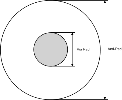
Increasing the via anti-pad diameter reduces the capacitive effects of the via and the overall insertion loss. Ensure that anti-pad diameter for vias on any high-speed signal are as large as possible (30 mils provides significant benefits without imposing undue implementation hardship). The copper clearance, indicated by this anti-pad, must be met on all layers where the via exists, including both routing layer and plane layers. The traces connecting to the via barrel contain the only copper allowed in this area; non-functional or unconnected via pads are not permitted. For an example of a via anti-pad diameter, see #SPRAAR71628.
 Figure 3-7 Anti-Pad
Diameter